Infiniti F50. Manual - part 155
REFRIGERANT LINES
ATC-145
C
D
E
F
G
H
I
K
L
M
A
B
ATC
Compressor Clutch
EJS000KF
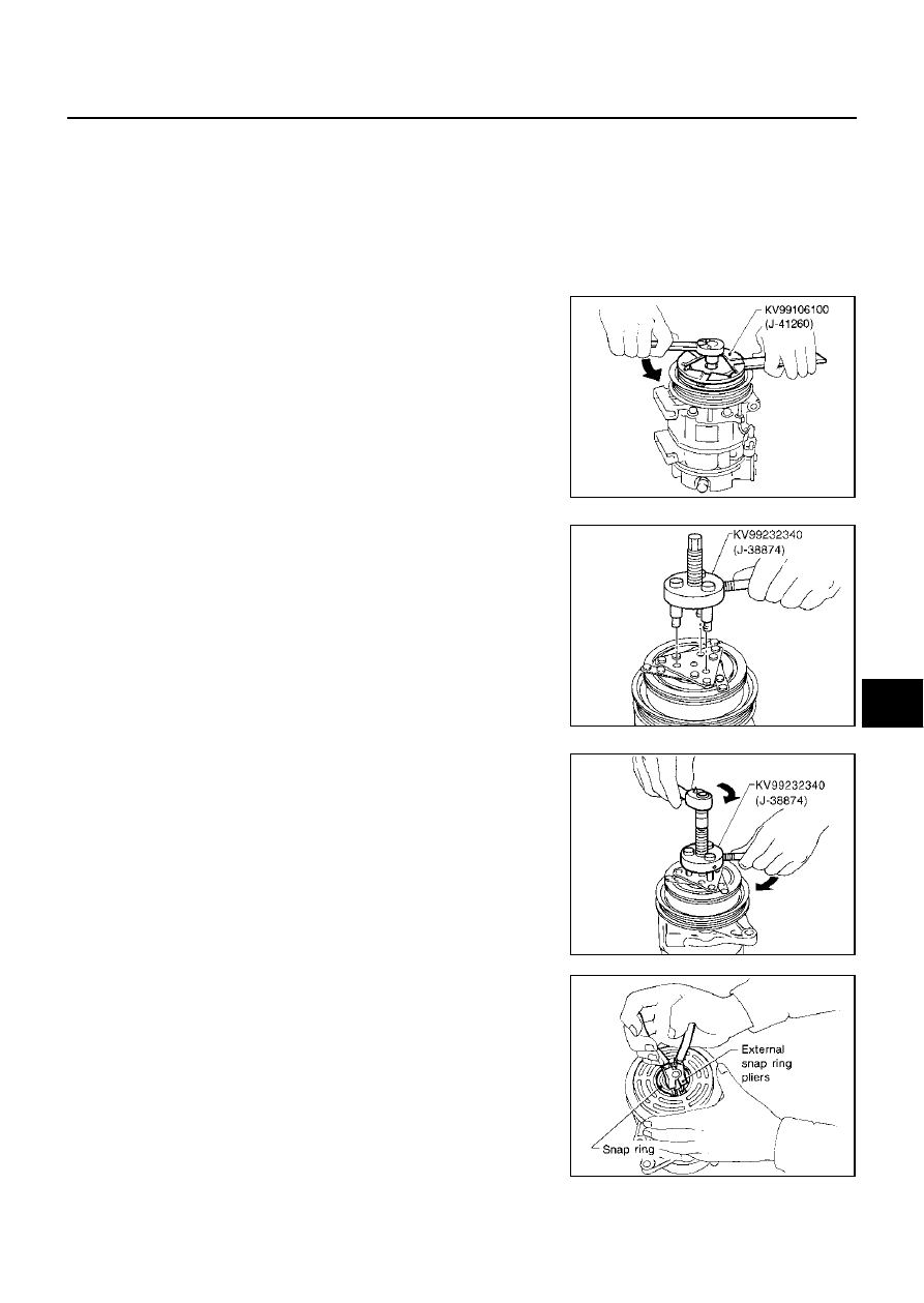
REMOVAL
Overhaul
1.
When removing center bolt, hold clutch disc with a wrench.
2.
Remove clutch disc using the clutch disc puller.
3.
Remove snap ring using external snap ring pliers.
Nut mounting the high-pressure flexible hose
Tightening torque
: 7.8 - 19.6 N·m (0.8 - 1.9 kg·m, 69 - 173 in-lb)
Nut mounting the low-pressure flexible hose
Tightening torque
: 7.8 - 19.6 N·m (0.8 - 1.9 kg·m, 69 - 173 in-lb)
RHA136EB
RHA399F
RHA124F
RHA138E