Infiniti F50. Manual - part 133


  Index      Infiniti     Infiniti F50 - service repair manual 2006 year


Search            


Content   ..  131  132  133  134   ..


Infiniti F50. Manual - part 133


TROUBLE DIAGNOSIS

ATC-57

C

D

E

F

G

H

I

K

L

M

A

B

ATC

Go to Air Mix Door Motor 

ATC-76, "DIAGNOSTIC PROCEDURE FOR AIR MIX DOOR

MOTOR"

 .

9. 

STEP-5: TEMPERATURE OF EACH SENSOR IS CHECKED

1.

Turn the temperature dial clockwise.

2.

Code No. 51 appears on the display.

>> GO TO 10.

10. 

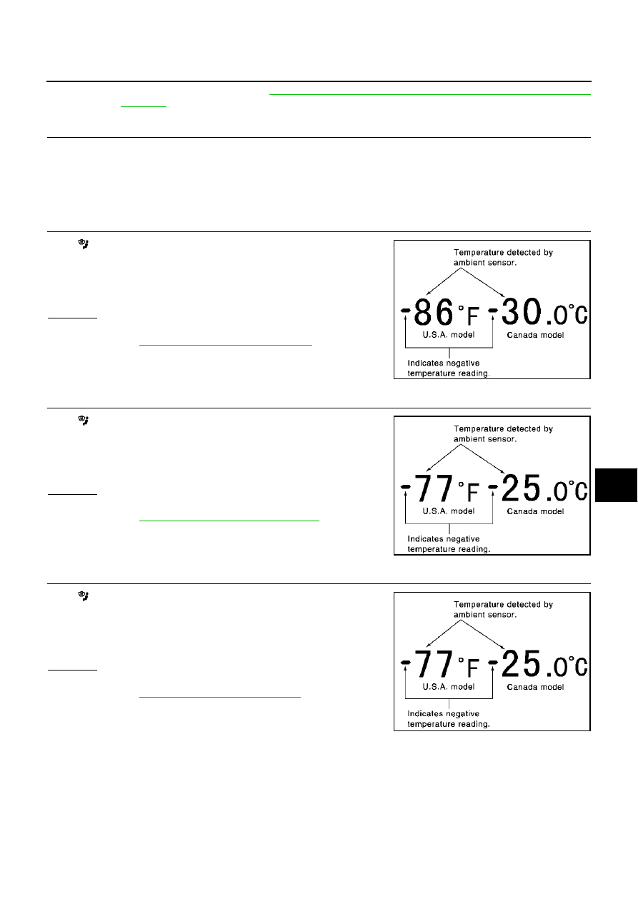
CHECK AMBIENT SENSOR

Press

(DEF) switch one time, temperature detected by ambient

sensor is indicated on the display.

NOTE:
If temperature shown on display greatly differs from actual tempera-
ture, check sensor circuit first, then inspect sensor.

OK or NG

OK

>> GO TO 11.

NG

>> Go to 

ATC-108, "Ambient Sensor Circuit"

 .

11. 

CHECK IN-VEHICLE SENSOR

Press

(DEF) switch the second time, temperature detected by in-

vehicle sensor is indicated on the display.

NOTE:
If temperature shown on display greatly differs from actual tempera-
ture, check sensor circuit first, then inspect sensor.

OK or NG

OK

>> GO TO 12.

NG

>> Go to 

ATC-110, "In-Vehicle Sensor Circuit"

 .

12. 

CHECK INTAKE SENSOR

Press

(DEF) switch the third time, temperature detected by intake

sensor is indicated on the display.

NOTE:
If temperature shown on display greatly differs from actual tempera-
ture, check sensor circuit first, then inspect sensor.

OK or NG

OK

>> GO TO 13.

NG

>> Go to 

ATC-116, "Intake Sensor Circuit"

 .

RJIA0223E

RJIA0224E

RJIA0225E

ATC-58

TROUBLE DIAGNOSIS

13. 

CHECK MULTIPLEX COMMUNICATION ERROR

1.

Press intake switch.

2.

Multiplex communication error between AV control unit (AV and
NAVI control unit) and auto amp. can be detected as self-diag-
nosis results.
(If plural errors occur, the display of each error will blink two
times for 0.5 second intervals.)

3.

Is multiplex communication error detected as self-diagnosis
results?

CAUTION:

Rear control cancel switch has two positions “CANCEL” and
“ON”. If rear control cancel switch has been canceled, Multiplex
communication error might be detected even there is no mal-
function.
So it is necessary to follow the procedure below:

1.

Switch “ON” position on the rear control cancel switch.

2.

Disconnect the battery negative terminal for approx. 10 seconds or more in other to delete the
memory of self-diagnosis.

3.

Reconfirm the multiplex communication error as self-diagnosis result is detected.

YES or NO

YES

>> Go to 

ATC-118, "Multiplex Communication Circuit"

 .

NO

>> 1. Turn ignition switch OFF or AUTO switch ON.

2. END

RJIA1589E

TROUBLE DIAGNOSIS

ATC-59

C

D

E

F

G

H

I

K

L

M

A

B

ATC

14. 

CHECK MALFUNCTIONING SENSOR

Refer to the following chart for malfunctioning code No.
(If two or more sensors malfunction, corresponding code Nos. blink respectively two times.)
*1: Conduct self-diagnosis STEP-2 under sunshine.
When conducting indoors, aim a light (more than 60W) at sunload sensor, otherwise Code No. 25 will indicate
despite that sunload sensor is functioning properly.

*2: 

ATC-108, "DIAGNOSTIC PROCEDURE FOR AMBIENT SENSOR"

 .

*3: 

ATC-111, "DIAGNOSTIC PROCEDURE FOR IN-VEHICLE SENSOR"

 .

*4: 

ATC-116, "DIAGNOSTIC PROCEDURE FOR INTAKE SENSOR"

 .

*5: 

ATC-113, "DIAGNOSTIC PROCEDURE FOR SUNLOAD SENSOR"

 .

*6: 

ATC-67, "DIAGNOSTIC PROCEDURE FOR LAN CIRCUIT"

 .

>> INSPECTION END

Code No.

Malfunctioning sensor (Including circuits)

Reference page

21 / -21

Ambient sensor

*2

22 / -22

In-vehicle sensor

*3

24 / -24

Intake sensor

*4

25 / -25

Sunload sensor

*5

26 / -26

Air mix door motor (LCU) PBR (Driver side)

*6

27 / -27

Air mix door motor (LCU) PBR (Passenger side)

*6

RJIA0227E

ATC-60

TROUBLE DIAGNOSIS

15. 

CHECK MALFUNCTIONING DOOR MOTOR POSITION SWITCH

Mode or (and) intake door motor position switch(es) is (are) malfunctioning.

(If two or more mode or intake doors are out of order, corresponding code numbers blink respectively two
times.)
*1: If mode door motor harness connector is disconnected, the following display pattern will appear.
31

32

33

34

35

36

Return to 31

*2: If intake door motor harness connector is disconnected, the following display pattern will appear.
37

38

39

Return to 37

*3

ATC-71, "Mode Door Motor Circuit"

 .

*4

ATC-77, "Intake Door Motor Circuit"

 .

>> INSPECTION END

Code No. *1 *2

Mode or intake door position

Reference page

31

VENT (Driver side)

Mode door motor

*3

32

FOOT (Driver side)

33

DEF (Driver side)

34

VENT (Passenger side)

35

FOOT1 (Passenger side)

36

DEF (Passenger side)

37

FRE

Intake door motor

*4

38

20%FRE

39

REC

RJIA0228E


Content   ..  131  132  133  134   ..