Infiniti F50. Manual - part 87
DTC P1846 ATF PRESSURE SWITCH 6
AT-233
D
E
F
G
H
I
J
K
L
M
A
B
AT
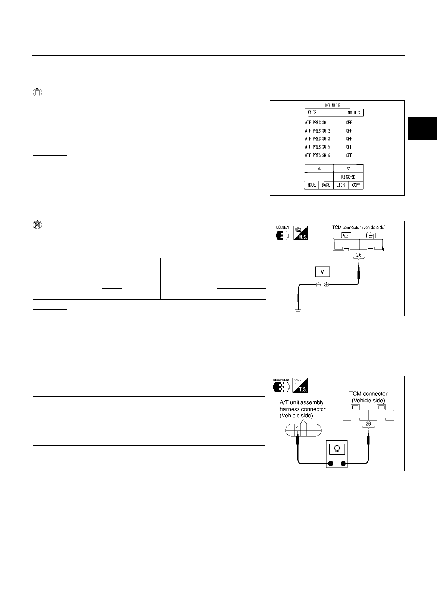
Diagnostic Procedure
ECS00894
1.
CHECK INPUT SIGNALS (WITH CONSULT-II)
With CONSULT-II
1.
Start engine.
2.
Select “ECU INPUT SIGNALS” or “MAIN SIGNALS” in “DATA
MONITOR” mode for “A/T” with CONSULT-II.
3.
Accelerate vehicle in the “D” position (2nd
Þ
3rd gear), and con-
firm the ON/OFF actuation of the “ATF PRES SW 6”.
OK or NG
OK
>> GO TO 5.
NG
>> GO TO 3.
2.
CHECK INPUT SIGNALS (WITHOUT CONSULT-II)
Without CONSULT-II
1.
Start engine.
2.
Accelerate vehicle in the “D” position (2nd
Þ
3rd gear).
OK or NG
OK
>> GO TO 5.
NG
>> GO TO 3.
3.
CHECK POWER SOURCE CIRCUIT
1.
Turn ignition switch to “OFF” position.
2.
Disconnect TCM connector.
3.
Check continuity between A/T unit assembly harness connector
and TCM connector.
4.
If OK, check harness for short to ground and short to power.
5.
Reinstall any part removed.
OK or NG
OK
>> GO TO 4.
NG
>> Repair open circuit or short to ground or short to power in harness or connectors.
PCIA0067E
Solenoid valve
Connector
No.
Terminal No.
(Wire color)
Voltage
High & low reverse
clutch solenoid valve
OFF
F104
26 (G/Y) - Ground
Battery voltage
ON
Approx. 0 V
PCIA0068E
Item
Connector No.
Terminal No.
(Wire color)
Continuity
TCM
F104
26 (G/Y)
Yes
A/T unit assembly harness
connector
F26
4 (G/Y)
SCIA3103E