Infiniti F50. Manual - part 65
DTC P1705 THROTTLE POSITION SENSOR
AT-145
D
E
F
G
H
I
J
K
L
M
A
B
AT
2.
CHECK DTC WITH TCM
With CONSULT-II
1.
Turn ignition switch to “ON” position. (Do not start engine.)
2.
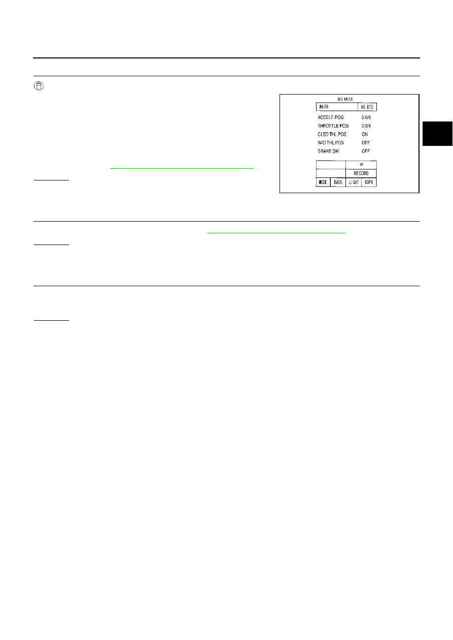
Select “ECU INPUT SIGNALS” in “DATA MONITOR” mode for
“A/T” with CONSULT-II.
3.
Depress accelerator pedal and read out the value of “ACCLE
POS” and “THROTTLE POSI”.
Check engine speed changes according to throttle position.
4.
Select “SELF-DIAG RESULTS” mode for “ENGINE” with CON-
SULT-II. Refer to
EC-112, "SELF-DIAG RESULTS MODE"
.
OK or NG
OK
>> GO TO 3.
NG
>> Repair or replace damaged parts.
3.
CHECK DTC
Perform “DTC Confirmation Procedure”. Refer to
AT-144, "DTC Confirmation Procedure"
.
OK or NG
OK
>> INSPECTION END
NG
>> GO TO 4.
4.
PERFORM TCM INSPECTION
1.
Perform TCM input/output signal inspection.
2.
If NG, recheck TCM pin terminals for damage or loose connection with harness connector.
OK or NG
OK
>> INSPECTION END
NG
>> Repair or replace damaged parts.
PCIA0070E