Infiniti F50. Manual - part 49
TROUBLE DIAGNOSIS
AT-81
D
E
F
G
H
I
J
K
L
M
A
B
AT
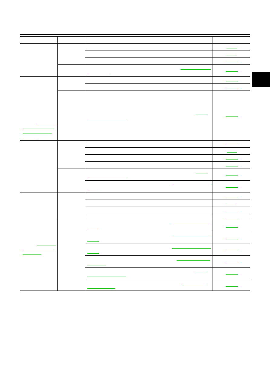
Extremely large
creep.
ON vehicle
1. Engine idle speed
2. CAN communication line
3. ATF pressure switch 5
OFF vehicle
4. Torque converter (ATF condition “NG” only. Refer to
With selector lever
in P position, vehi-
cle does not enter
parking condition
or, with selector
lever in another
position, parking
condition is not
cancelled.
Refer to
“P” Position, Vehi-
cle Moves When
Pushed"
ON vehicle
1. PNP switch
2. Control linkage adjustment
OFF vehicle
3. Parking pawl components (ATF condition “NG” only. Refer to
.)
Vehicle runs with
transmission in “ P”
position.
ON vehicle
1. PNP switch
2. Fluid level and state
3. Control linkage adjustment
4. Control valve assembly
OFF vehicle
5. Parking pawl components (ATF condition “NG” only. Refer to
.)
6. Gear system (ATF condition “NG” only. Refer to
.)
Vehicle runs with
transmission in “N”
position.
Refer to
ON vehicle
1. PNP switch
2. Fluid level and state
3. Control linkage adjustment
4. Control valve assembly
OFF vehicle
5. Input clutch (ATF condition “NG” only. Refer to
.)
6. Gear system (ATF condition “NG” only. Refer to
.)
7. Direct clutch (ATF condition “NG” only. Refer to
.)
8. Reverse brake (ATF condition “NG” only. Refer to
.)
9. Forward one-way clutch* (ATF condition “NG” only. Refer to
.)
10. Low coast brake* (ATF condition “NG” only. Refer to
.)
Symptom
Condition
Diagnostic Item
Reference page