Infiniti I35 (A33). Manual - part 591
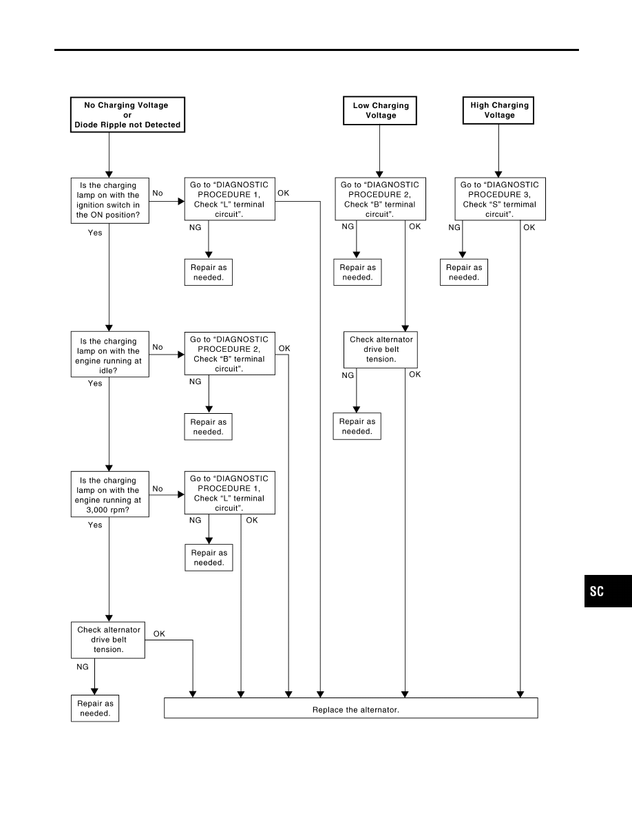
WORK FLOW
NHSC0020S02
SEL423X
GI
MA
EM
LC
EC
FE
AT
AX
SU
BR
ST
RS
BT
HA
EL
IDX
CHARGING SYSTEM
Trouble Diagnoses with Battery/Starting/Charging System Tester (Cont’d)
SC-25
|
|
|
WORK FLOW NHSC0020S02 SEL423X GI MA EM LC EC FE AT AX SU BR ST RS BT HA EL IDX CHARGING SYSTEM Trouble Diagnoses with Battery/Starting/Charging System Tester (Cont’d) SC-25 |