Infiniti I35 (A33). Manual - part 559
SLC031B
2.
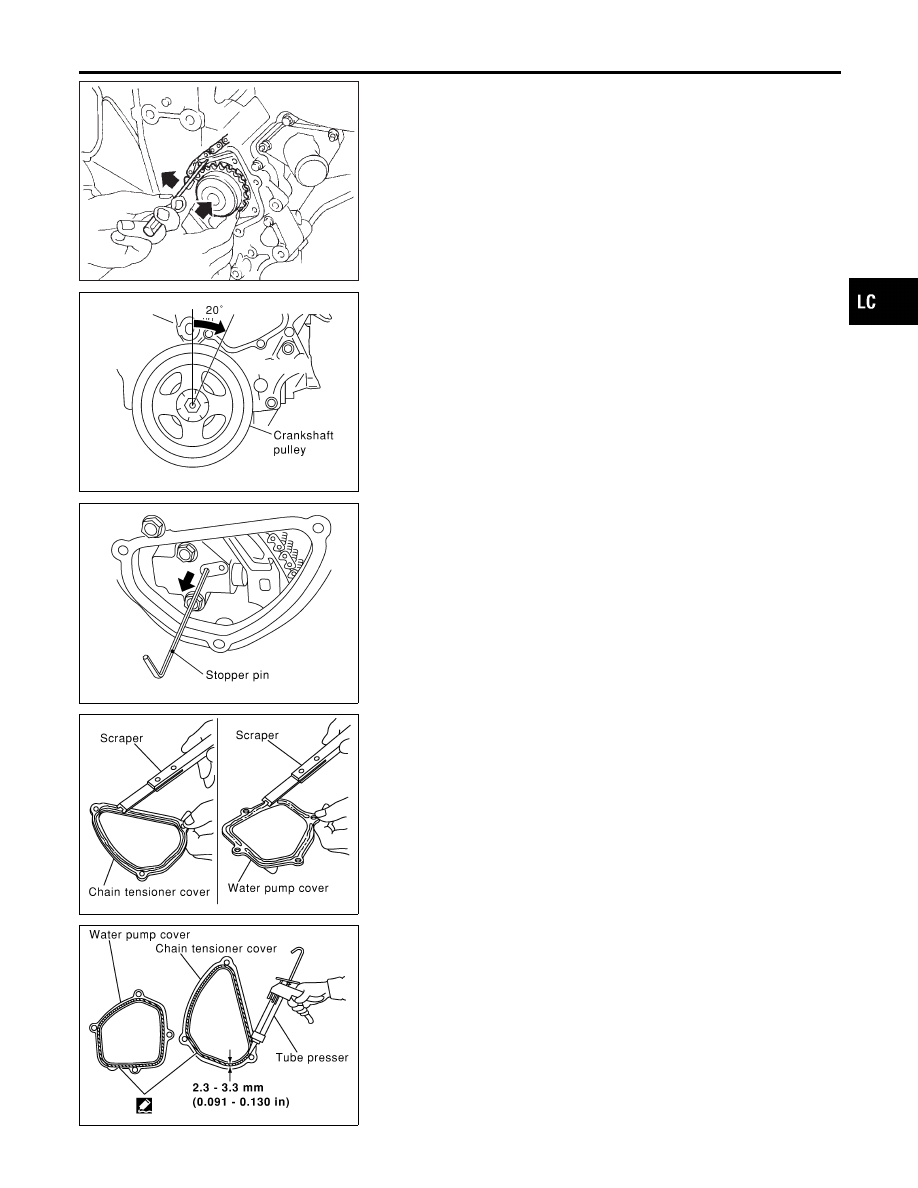
Install water pump.
I
Do not allow cylinder block to nip O-rings when installing
water pump.
SLC445B
3.
Return the crankshaft pulley to its original position by turning
it 20° forward.
SLC448B
4.
Install timing chain tensioner, then remove the stopper pin.
I
When installing the timing chain tensioner, engine oil
should be applied to the oil hole and tensioner.
SLC446B
5.
Install chain tensioner cover and water pump cover.
a.
Before installing, remove all traces of liquid gasket from mat-
ing surface of water pump cover and chain tensioner cover
using a scraper.
Also remove traces of liquid gasket from mating surface of
front cover.
SLC447B
b.
Apply a continuous bead of liquid gasket to mating surface of
chain tensioner cover and water pump cover.
6.
Install drain plug on cylinder block.
7.
Reinstall any parts removed in reverse order of removal.
I
After starting engine, let idle for three minutes, then rev
engine up to 3,000 rpm under no load to purge air from the
high-pressure chamber of the chain tensioners. The
engine may produce a rattling noise. This indicates that
air still remains in the chamber and is not a matter of
concern.
GI
MA
EM
EC
FE
AT
AX
SU
BR
ST
RS
BT
HA
SC
EL
IDX
ENGINE COOLING SYSTEM
Water Pump (Cont’d)
LC-17