Infiniti I35 (A33). Manual - part 538
RHA385H
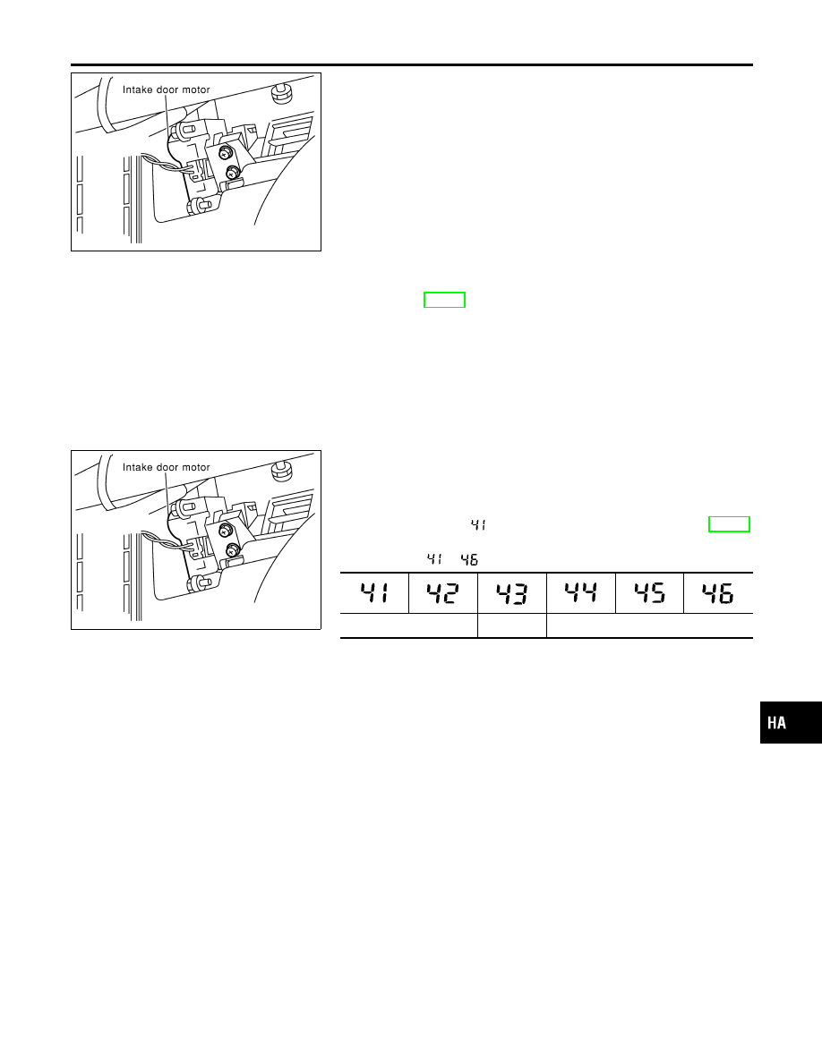
COMPONENT DESCRIPTION
NHHA0193
The intake door motor is attached to the intake unit. It rotates so
that air is drawn from inlets set by the auto amplifier. Motor rota-
tion is conveyed to a lever which activates the intake door.
DIAGNOSTIC PROCEDURE
NHHA0194
SYMPTOM: Intake door motor does not operate normally.
I
Refer to HA-55.
RHA385H
CONTROL LINKAGE ADJUSTMENT
NHHA0195
Intake Door
NHHA0195S01
1.
Install intake door motor on intake unit and connect it to main
harness.
2.
Set up code No.
in Self-diagnosis STEP-4. Refer to HA-37.
3.
Make sure intake door operates properly when changing from
code No.
to
by pushing DEF switch.
REC
20% FRE
FRE
GI
MA
EM
LC
EC
FE
AT
AX
SU
BR
ST
RS
BT
SC
EL
IDX
TROUBLE DIAGNOSES
Intake Door Motor (Cont’d)
HA-65