Infiniti I35 (A33). Manual - part 531


  Index      Infiniti     Infiniti I35 (A33) - service repair manual 2004 year


Search            


Content   ..  529  530  531  532   ..


Infiniti I35 (A33). Manual - part 531


FUNCTION CONFIRMATION PROCEDURE

NHHA0176S02

1

ENTER SELF-DIAGNOSTIC MODE

Perform steps 1 - 3
1. Turn the ignition OFF.
2. Start the engine.
3. Immediately after starting the engine press and hold the OFF switch (for the auto A/C system) for at least 5 seconds.
The A/C Auto Amp. should now be in Self Diagnosis mode. Self Diagnosis steps 1 - 5 can now be performed. Self Diagno-
sis step-1 will be displayed first. Shifting from one step to another is accomplished by turning the TEMP dial clockwise or
counterclockwise.

©

GO TO 2.

2

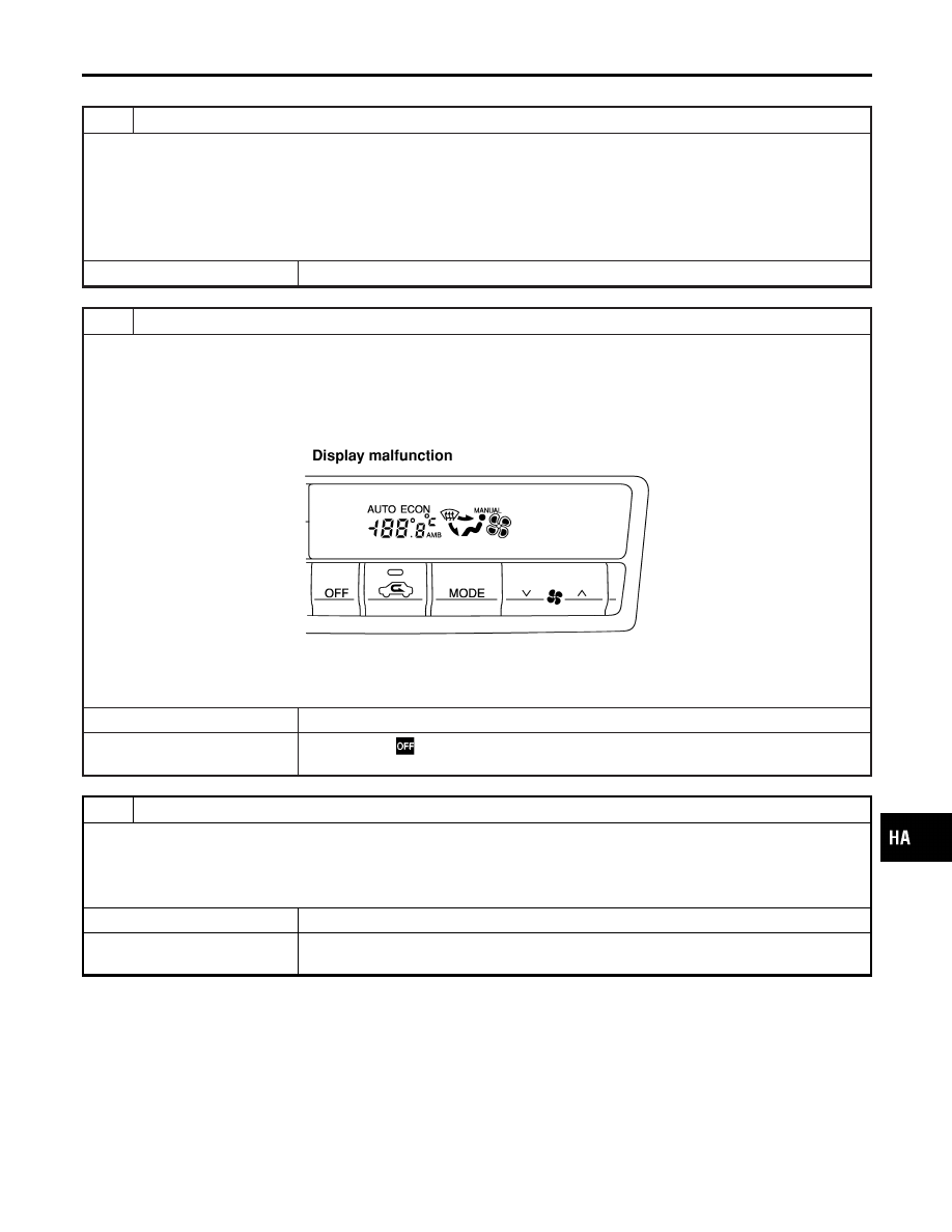
STEP-1 LED/DISPLAY CHECK

Verify all segments illuminate.
If all segments do not illuminate the fluorescent display tube is malfunctioning or the system has not entered self diagnosis
which would indicate a malfunctioning OFF switch.
Do all LEDs and segments illuminate?

RHA093I

Yes or No

Yes

©

GO TO 3.

No

©

Malfunctioning

switch, LED or fluorescent display tube.

Replace A/C auto amp.

3

CHECK TO ADVANCE SELF-DIAGNOSIS STEP-2

1. Turn the TEMP dial clockwise.
2. Advance to self-diagnosis STEP-2.
If the system does not shift between step-1 and 2 a malfunctioning TEMP dial is indicated.

Yes or No

Yes

©

GO TO 4.

No

©

Malfunctioning TEMP dial.
Replace A/C auto amp.

GI

MA

EM

LC

EC

FE

AT

AX

SU

BR

ST

RS

BT

SC

EL

IDX

TROUBLE DIAGNOSES

Self-diagnosis (Cont’d)

HA-37

4

CHECK TO RETURN SELF-DIAGNOSIS STEP-1

1. Turn the TEMP dial counterclockwise.
2. Return to self-diagnosis STEP-1.
If the system does not shift between step-1 and 2 a malfunctioning TEMP dial is indicated.

Yes or No

Yes

©

GO TO 5.

No

©

Malfunctioning TEMP dial.
Replace A/C auto amp.

5

STEP-2 SENSOR CIRCUITS ARE CHECKED FOR OPEN OR SHORT CIRCUIT

Turn the TEMP dial clockwise, advance to STEP-2: Wait (about 25 seconds) for two digit code to appear.
This is the electronic sensor input check which includes circuits.
Does code No.

appear on the display?

RHA970DB

Yes or No

Yes

©

GO TO 6.

No

©

GO TO 13.

6

STEP-3 MODE DOOR AND INTAKE DOOR POSITIONS ARE CHECKED

Turn the TEMP dial clockwise, advance to STEP-3. Wait (about 50 seconds) for two digit code to appear.
This is the mode door and intake door position switch input checks including circuits.
Does code No.

appear on the display?

RHA869DD

Yes or No

Yes

©

GO TO 7.

No

©

GO TO 14.

TROUBLE DIAGNOSES

Self-diagnosis (Cont’d)

HA-38

7

STEP-4 OPERATION OF EACH ACTUATOR IS CHECKED

Turn the TEMP dial clockwise, advance to STEP-4.
Engine running.
This is Heater and A/C system check. Code 41 will be displayed. Use the DEF switch to advance the code number from
41 to 46. After 46, the display will return to code 41 and can be advanced to 46 again.

RHA495A

©

GO TO 8.

GI

MA

EM

LC

EC

FE

AT

AX

SU

BR

ST

RS

BT

SC

EL

IDX

TROUBLE DIAGNOSES

Self-diagnosis (Cont’d)

HA-39

8

CHECK ACTUATORS

Confirm operation of system components according to the following charts.
Checks must be made visually, by listening to any noise, or by touching air outlets with your hand, etc. for
improper operation.

MTBL0314

Operating condition of each actuator cannot be checked by indicators.

MTBL0128

OK or NG

OK

©

GO TO 9.

NG

©

I

Air outlet does not change.
Go to “Mode Door Motor” (HA-53).

I

Intake door does not change.
Go to “Intake Door Motor” (HA-63).

I

Discharge air temperature does not change.
Go to “Air Mix Door Motor” (HA-60).

I

Blower motor operation is malfunctioning.
Go to “Blower Motor” (HA-66).

I

Magnet clutch does not engage.
Go to “Magnet Clutch” (HA-75).

TROUBLE DIAGNOSES

Self-diagnosis (Cont’d)

HA-40


Content   ..  529  530  531  532   ..