Infiniti I35 (A33). Manual - part 527


  Index      Infiniti     Infiniti I35 (A33) - service repair manual 2004 year


Search            


Content   ..  525  526  527  528   ..


Infiniti I35 (A33). Manual - part 527


RHA351H

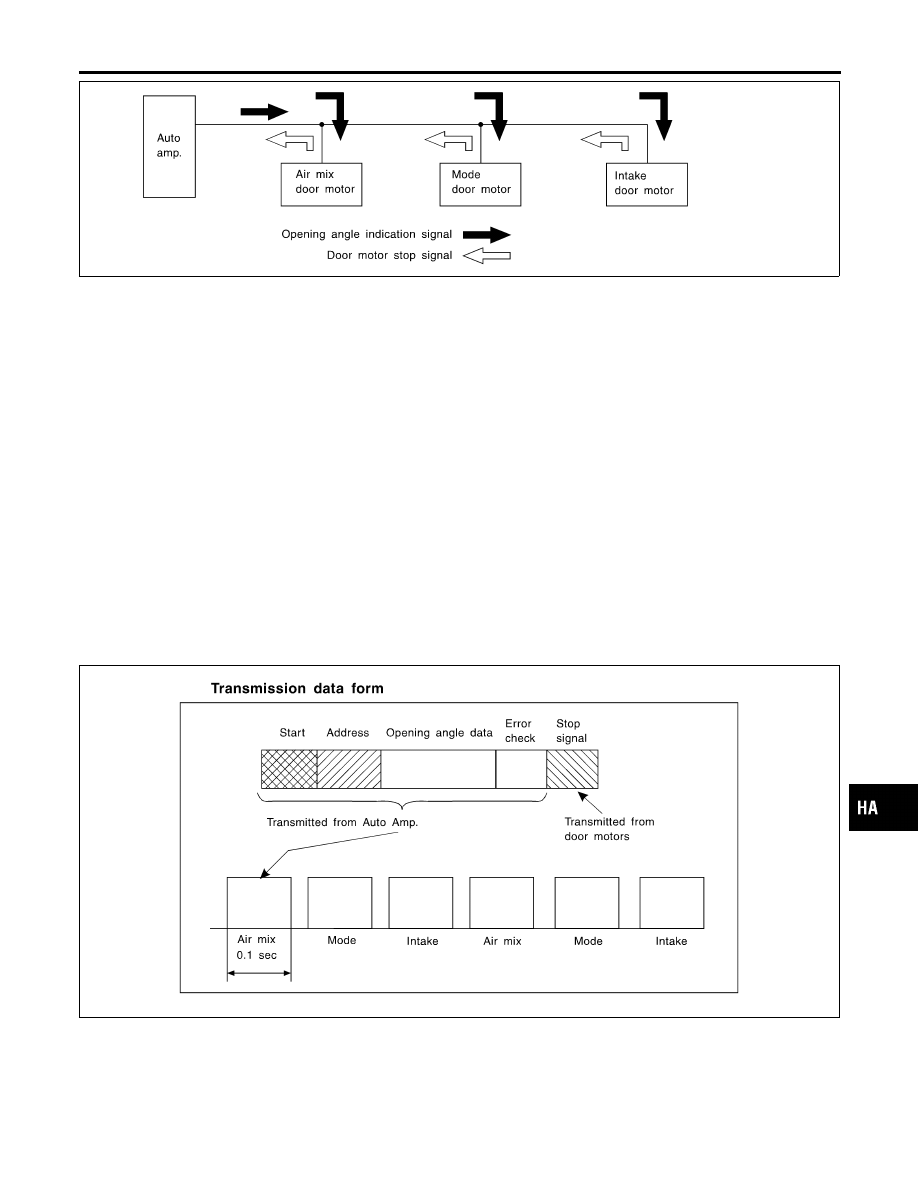
Transmission Data and Transmission Order

NHHA0168S0102

Amplifier data is transmitted consecutively to each of the door motors following the form shown in figure below.
Start: Initial compulsory signal sent to each of the door motors.
Address: Data sent from the auto amplifier is selected according to data-based decisions made by the air mix
door motor, intake door motor and mode door motor.
If the addresses are identical, the opening angle data and error check signals are received by the door motor
LCUs. The LCUs then make the appropriate error decision. If the opening angle data is normal, door control
begins.
If an error exists, the received data is rejected and corrected data received. Finally, door control is based upon
the corrected opening angle data.
Opening angle: Data that shows the indicated door opening angle of each door motor.
Error check: Procedure by which sent and received data is checked for errors. Error data is then compiled.
The error check prevents corrupted data from being used by the air mix door motor, mode door motor and
intake door motor. Error data can be related to the following problems.

I

Abnormal electrical frequency

I

Poor electrical connections

I

Signal leakage from transmission lines

I

Signal level fluctuation

Stop signal: At the end of each transmission, a stop operation, in-operation, or internal problem message is
delivered to the auto amplifier. This completes one data transmission and control cycle.

RHA352H

Air Mix Door Control (Automatic Temperature Control)

NHHA0168S0103

The air mix door is automatically controlled so that in-vehicle temperature is maintained at a predetermined
value by: The temperature setting, ambient temperature, in-vehicle temperature and amount of sunload.

GI

MA

EM

LC

EC

FE

AT

AX

SU

BR

ST

RS

BT

SC

EL

IDX

DESCRIPTION

Features (Cont’d)

HA-21

Fan Speed Control

NHHA0168S0104

Blower speed is automatically controlled based on temperature setting, ambient temperature, in-vehicle
temperature, intake temperature, amount of sunload and air mix door position.
With FAN switch set to “AUTO”, the blower motor starts to gradually increase air flow volume.
When engine coolant temperature is low, the blower motor operation is delayed to prevent cool air from flow-
ing.

Intake Door Control

NHHA0168S0105

The intake doors are automatically controlled based on temperature setting, ambient temperature, in-vehicle
temperature, intake temperature, amount of sunload, air mix door position and ON-OFF operation of the com-
pressor.

Outlet Door Control

NHHA0168S0106

The outlet door is automatically controlled by: The temperature setting, ambient temperature, in-vehicle
temperature, intake temperature and amount of sunload.

Magnet Clutch Control

NHHA0168S0107

The ECM controls compressor operation using input signals from the throttle position sensor, refrigerant pres-
sure sensor and auto amplifier.

Self-diagnostic System

NHHA0168S0108

The self-diagnostic system is built into the auto amplifier (LCU) to quickly locate the cause of problems.

DESCRIPTION

Features (Cont’d)

HA-22

Overview of Control System

=NHHA0169

The control system consists of input sensors, switches, the automatic amplifier (microcomputer) and outputs.
The relationship of these components is shown in the diagram below:

RHA032IA

Control Operation

NHHA0170

RHA033IA

GI

MA

EM

LC

EC

FE

AT

AX

SU

BR

ST

RS

BT

SC

EL

IDX

DESCRIPTION

Overview of Control System

HA-23

DISPLAY SCREEN

NHHA0170S01

Displays the operational status of the system.

AUTO SWITCH

NHHA0170S02

The compressor, intake doors, air mix door, outlet doors, and blower speed are automatically controlled so
that the in-vehicle temperature will reach, and be maintained at the set temperature selected by the operator.

ECON SWITCH

NHHA0170S03

By pressing the ECON switch, the display should indicate ECON and the compressor always turns OFF. With
the compressor OFF, the system will not remove heat (cool) or de-humidify. The system will maintain the in-
vehicle temperature at the set temperature when the set temperature is above the ambient (outside) tempera-
ture. The system will set the intake doors to the outside air position.

TEMPERATURE DIAL (POTENTIO TEMPERATURE CONTROL)

NHHA0170S04

Increases or decreases the set temperature.

OFF SWITCH

NHHA0170S05

The compressor and blower are OFF, the intake doors are set to the outside air position, and the air outlet
doors are set to the foot (80% foot and 20% defrost) position.

FAN SWITCH

NHHA0170S06

Manual control of the blower speed. Four speeds are available for manual control (as shown on the display
screen):
low

, medium low

, medium high

, high

RECIRCULATION (REC) SWITCH

NHHA0170S07

OFF position: Outside air is drawn into the passenger compartment.
ON position: Interior air is recirculated inside the vehicle.

DEFROSTER (DEF) SWITCH

NHHA0170S08

Positions the air outlet doors to the defrost position. Also positions the intake doors to the outside air position.

MODE SWITCH

NHHA0170S09

Control the air discharge outlets.

REAR WINDOW DEFOGGER SWITCH

NHHA0170S10

When illumination is ON, rear window is defogged.

DESCRIPTION

Control Operation (Cont’d)

HA-24


Content   ..  525  526  527  528   ..