Infiniti I35 (A33). Manual - part 526


  Index      Infiniti     Infiniti I35 (A33) - service repair manual 2004 year


Search            


Content   ..  524  525  526  527   ..


Infiniti I35 (A33). Manual - part 526


Operation

=NHHA0164S02

1. Operation Control Valve

NHHA0164S0201

Operation control valve is located in the suction port (low-pressure) side, and opens or closes in response to
changes in refrigerant suction pressure.
Operation of the valve controls the internal pressure of the crankcase.
The angle of the swash plate is controlled between the crankcase’s internal pressure and the piston cylinder
pressure.
2. Maximum Cooling

NHHA0164S0202

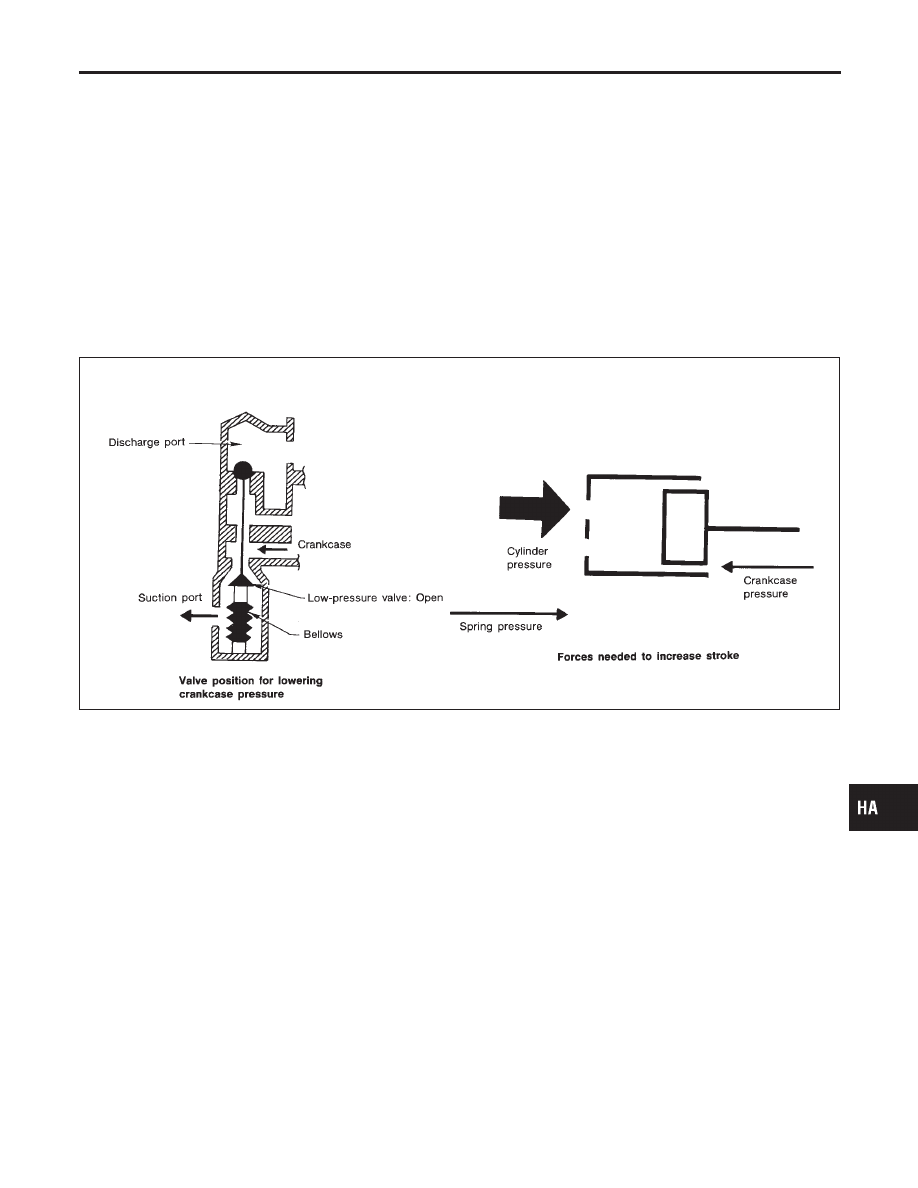
Refrigerant pressure on the low-pressure side increases with an increase in heat loads.
When this occurs, the control valve’s bellows compress to open the low-pressure side valve and close the
high-pressure side valve.
This causes the following pressure changes:

I

the crankcase’s internal pressure to equal the pressure on the low-pressure side;

I

the cylinder’s internal pressure to be greater than the crankcase’s internal pressure.

Under this condition, the swash plate is set to the maximum stroke position.

RHA473C

GI

MA

EM

LC

EC

FE

AT

AX

SU

BR

ST

RS

BT

SC

EL

IDX

DESCRIPTION

V-6 Variable Displacement Compressor (Cont’d)

HA-17

3. Capacity Control

=NHHA0164S0203

I

Refrigerant pressure on suction side is low during high speed driving or when ambient or interior tempera-
ture is low.

I

The bellows expands when refrigerant pressure on the suction pressure side drops below approximately
177 kPa (1.8 kg/cm

2

, 26 psi).

Since suction pressure is low, it makes the suction port close and the discharge port open. Thus, crank-
case pressure becomes high as high pressure enters the crankcase.

I

The force acts around the journal pin near the swash plate, and is generated by the pressure difference
before and behind the piston.
The drive lug and journal pin are located where the piston generates the highest pressure. Piston pres-
sure is between suction pressure Ps and discharge pressure Pd, which is near suction pressure Ps. If
crankcase pressure Pc rises due to capacity control, the force around the journal pin makes the swash
plate angle decrease and also the piston stroke decrease. In other words, crankcase pressure increase
triggers pressure difference between the piston and the crankcase. The pressure difference changes the
angle of the swash plate.

RHA474C

DESCRIPTION

V-6 Variable Displacement Compressor (Cont’d)

HA-18

Component Layout

NHHA0166

RHA349H

GI

MA

EM

LC

EC

FE

AT

AX

SU

BR

ST

RS

BT

SC

EL

IDX

DESCRIPTION

Component Layout

HA-19

Introduction

NHHA0167

AIR CONDITIONER LAN SYSTEM OVERVIEW CONTROL SYSTEM

NHHA0167S01

The LAN system consists of auto amp., air mix door motor, mode door motor and intake door motor.
A configuration of these components is shown in the diagram below.

RHA439GC

Features

NHHA0168

SYSTEM CONSTRUCTION (LAN)

NHHA0168S01

A small network is constructed between the auto amplifier, air mix door motor, mode door motor and intake
door motor. The auto amplifier and motors are connected by data transmission lines and motor power supply
lines. The LAN network is built through the ground circuits of the three motors.
Addresses, motor opening angle signals, motor stop signals and error checking messages are all transmitted
through the data transmission lines connecting the auto amplifier and three motors.
The following functions are contained in LCUs built into the air mix door motor, intake door motor and the mode
door motor.

I

Address

I

Motor opening angle signals

I

Data transmission

I

Motor stop and drive decision

I

Opening angle sensor (PBR function)

I

Comparison

I

Decision (Auto amplifier indicated value and motor opening angle comparison)

RHA350H

Operation

NHHA0168S0101

The auto amplifier receives data from each of the sensors. The amplifier sends air mix door, mode door and
intake door opening angle data to the air mix door motor LCU, mode door LCU and intake door motor LCU.
The air mix door motor, mode door motor and intake door motor read their respective signals according to the
address signal. Opening angle indication signals received from the auto amplifier and each of the motor posi-
tion sensors are compared by the LCUs in each motor with the existing decision and opening angles.
Subsequently, HOT/COLD, FRESH/RECIRCULATION or DEFROST/VENT operation is selected. The new
selection data is returned to the auto amplifier.

DESCRIPTION

Introduction

HA-20


Content   ..  524  525  526  527   ..