Infiniti I35 (A33). Manual - part 523
O-RING AND REFRIGERANT CONNECTION
NHHA0156S02
RHA030I
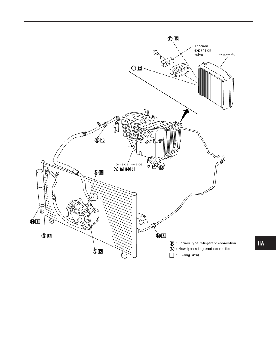
CAUTION:
The new and former refrigerant connections use different O-ring configurations. Do not confuse
O-rings since they are not interchangeable. If a wrong O-ring is installed, refrigerant will leak at, or
around, the connection.
GI
MA
EM
LC
EC
FE
AT
AX
SU
BR
ST
RS
BT
SC
EL
IDX
PRECAUTIONS
Precautions for Refrigerant Connection (Cont’d)
HA-5