Infiniti I35 (A33). Manual - part 514
Engine Compartment
There are several reasons a vehicle or engine vibration could
cause an electrical complaint. Some of the things to check for are:
I
Connectors not fully seated.
I
Wiring harness not long enough and is being stressed due to
engine vibrations or rocking.
I
Wires laying across brackets or moving components.
I
Loose, dirty or corroded ground wires.
I
Wires routed too close to hot components.
To inspect components under the hood, start by verifying the integ-
rity of ground connections. (Refer to GROUND INSPECTION
described later.) First make sure that the system is properly
grounded. Then check for loose connection by gently shaking the
wiring or components as previously explained. Using the wiring
diagrams inspect the wiring for continuity.
Behind The Instrument Panel
An improperly routed or improperly clamped harness can become
pinched during accessory installation. Vehicle vibration can aggra-
vate a harness which is routed along a bracket or near a screw.
Under Seating Areas
An unclamped or loose harness can cause wiring to be pinched by
seat components (such as slide guides) during vehicle vibration. If
the wiring runs under seating areas, inspect wire routing for pos-
sible damage or pinching.
SGI842
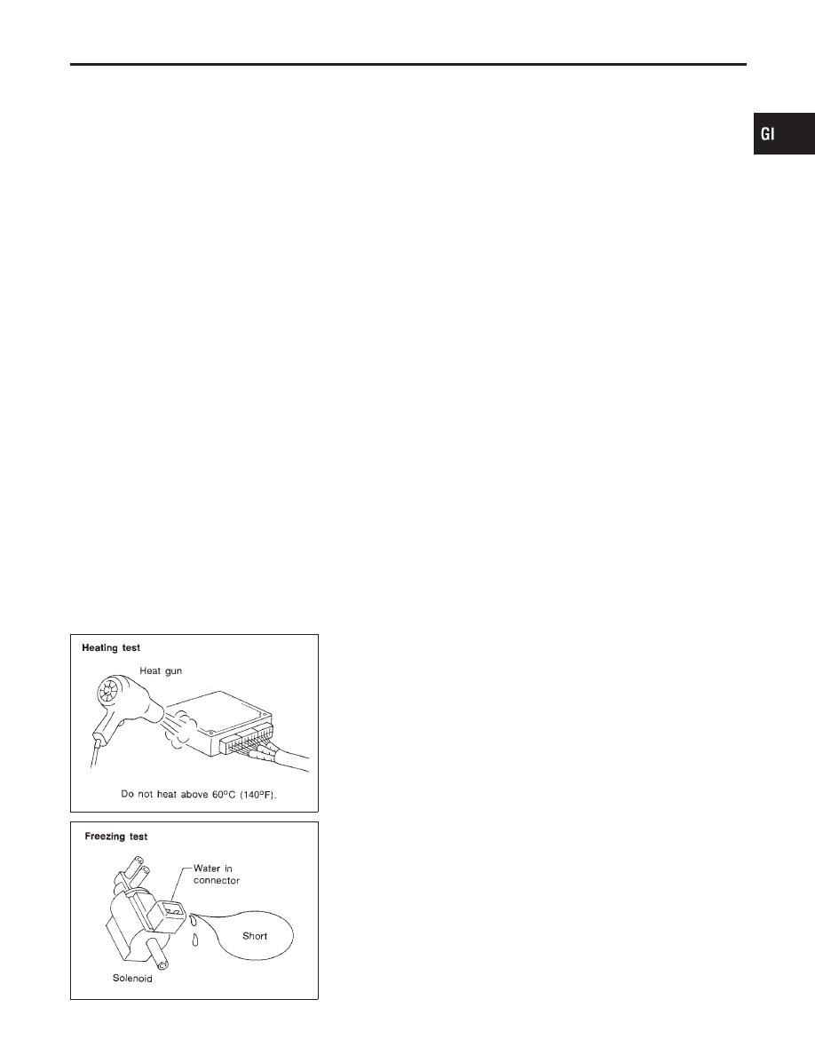
HEAT SENSITIVE
NHGI0005S0203
The owner’s incident may occur during hot weather or after car has
sat for a short time. In such cases you will want to check for a heat
sensitive condition.
To determine if an electrical component is heat sensitive, heat the
component with a heat gun or equivalent.
Do not heat components above 60°C (140°F). If incident occurs
while heating the unit, either replace or properly insulate the com-
ponent.
SGI843
FREEZING
NHGI0005S0204
The customer may indicate the incident goes away after the car
warms up (winter time). The cause could be related to water freez-
ing somewhere in the wiring/electrical system.
There are two methods to check for this. The first is to arrange for
the owner to leave his car overnight. Make sure it will get cold
enough to demonstrate his complaint. Leave the car parked out-
side overnight. In the morning, do a quick and thorough diagnosis
of those electrical components which could be affected.
MA
EM
LC
EC
FE
AT
AX
SU
BR
ST
RS
BT
HA
SC
EL
IDX
HOW TO PERFORM EFFICIENT DIAGNOSIS FOR AN ELECTRICAL INCIDENT
Incident Simulation Tests (Cont’d)
GI-27