Infiniti I35 (A33). Manual - part 512
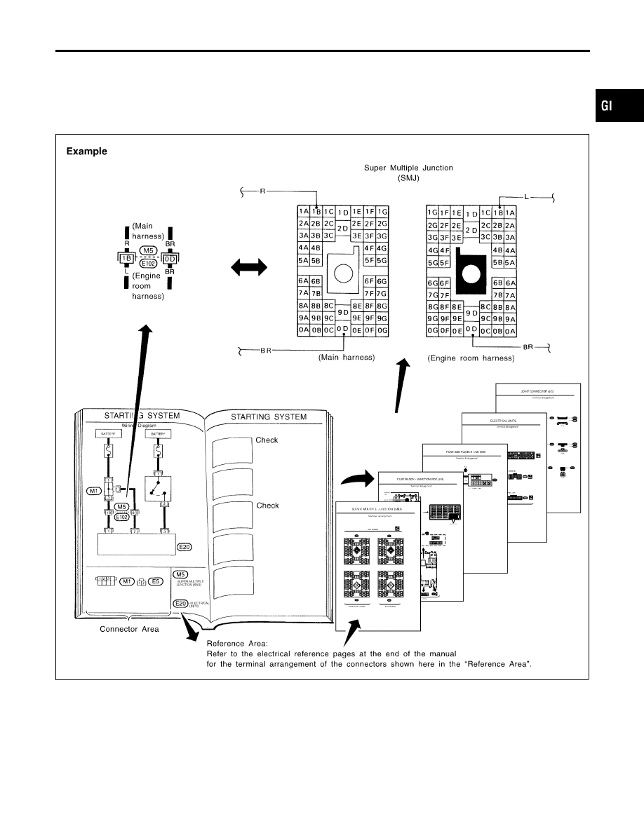
REFERENCE AREA
=NHGI0003S0207
The Reference Area of the wiring diagram contains references to
additional electrical reference pages at the end of the manual. If
connector numbers and titles are shown in the Reference Area of
the wiring diagram, these connector symbols are not shown in the
Connector Area.
SGI092A
Super multiple junction (SMJ)
In a wiring diagram, the SMJ connectors include a letter of the
alphabet in the terminal number.
SMJ connector numbers are shown in the Reference Area of the
wiring diagram. SMJ terminal arrangement can be found on the
electrical reference pages at the end of the manual. For terminal
arrangement of these connectors, refer to the “SUPER MULTIPLE
JUNCTION (SMJ)” electrical reference page at the end of the
MA
EM
LC
EC
FE
AT
AX
SU
BR
ST
RS
BT
HA
SC
EL
IDX
HOW TO READ WIRING DIAGRAMS
Description (Cont’d)
GI-19