Infiniti I35 (A33). Manual - part 480


  Index      Infiniti     Infiniti I35 (A33) - service repair manual 2004 year


Search            


Content   ..  478  479  480  481   ..


Infiniti I35 (A33). Manual - part 480


SEM709G

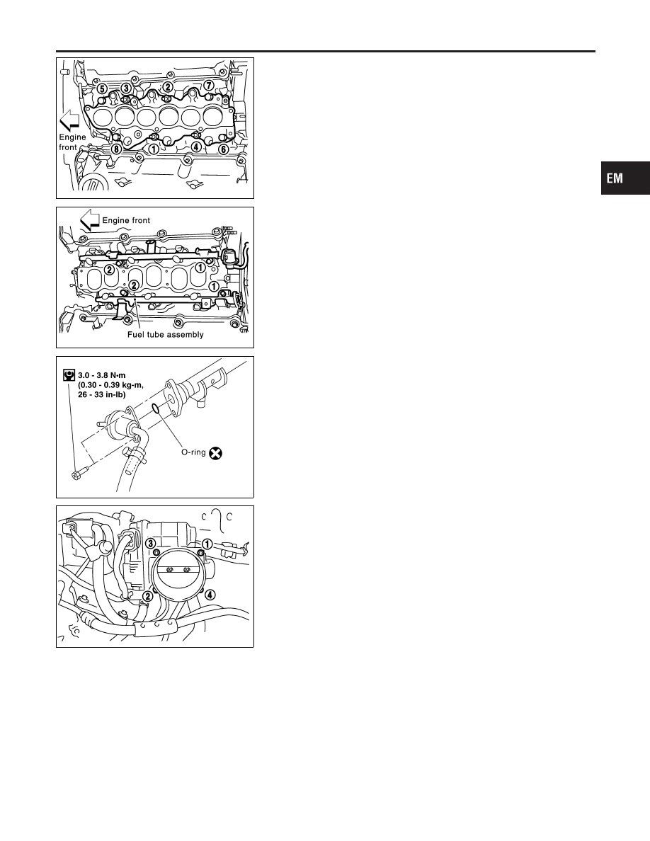
TIGHTENING PROCEDURES

NHEM0006S01

Intake Manifold

NHEM0006S0101

I

Loosen in reverse order shown in the figure.

I

Tighten in numerical order shown in the figure.

1.

Tighten all bolts and nuts to 4.9 to 9.8 N·m (0.50 to 0.99 kg-m,
4 to 7 ft-lb).

2.

Finally tighten all bolts and nuts to 26.5 to 31.4 N·m (2.7 to 3.2
kg-m, 20 to 23 ft-lb).

I

Tighten all bolts and nuts to the final torque, evenly dividing the
tightening into at least three steps.

SEM710G

Fuel Tube

NHEM0006S0102

I

Tighten in numerical order shown in the figure.

1.

Tighten all bolts to 9.3 to 10.8 N·m (0.95 to 1.1 kg-m, 6.9 to
7.9 ft-lb).

2.

Then tighten all bolts to 20.6 to 26.5 N·m (2.1 to 2.7 kg-m, 16
to 19 ft-lb).

SEM952F

Fuel Damper

NHEM0006S0103

Tighten fuel damper to 2.9 to 3.8 N·m (0.3 to 0.39 kg-m, 26.0 to
33.9 in-lb).

I

Tighten screws evenly several times to have the fuel
damper tightened at the specified torque.

I

Always replace O-ring with new ones.

I

Lubricate O-ring with new engine oil.

SEM711G

Electronic Control Throttle Actuator

NHEM0006S0105

I

Tighten in numerical order shown in the figure.

Tighten all bolts to 7.2 to 9.6 N·m (0.74 to 0.97 kg-m, 64 to 84 in-
lb).

CAUTION:

I

Perform “Throttle Valve Closed Position Learning” when
harness connector of electronic throttle control actuator
is disconnected.
Refer to “BASIC SERVICE PROCEDURE” in EC section.

I

Perform “Idle Air Volume Learning” when electronic
throttle control actuator is replaced.
Refer to “BASIC SERVICE PROCEDURE” in EC section.

GI

MA

LC

EC

FE

AT

AX

SU

BR

ST

RS

BT

HA

SC

EL

IDX

OUTER COMPONENT PARTS

Removal and Installation (Cont’d)

EM-11

SEM712G

Intake Manifold Upper Collector

NHEM0006S0108

I

Loosen in reverse order and tighten in numerical order
shown in the figure.
Tighten all bolts to 17.6 to 21.6 N·m (1.8 to 2.2 kg-m, 13 to 15
ft-lb).

SEM713G

Intake Manifold Lower Collector

NHEM0006S0107

I

Loosen in reverse order shown in the figure.

I

Tighten in numerical order shown in the figure.

Tighten bolts and nuts to 17.6 to 21.6 N·m (1.8 to 2.2 kg-m, 13 to
15 ft-lb).

SEM714G

Power Valve

NHEM0006S0109

I

Tighten in numerical order shown in the figure.
Tighten all bolts to 17.6 to 21.6 N·m (1.8 to 2.2 kg-m, 13 to 15
ft-lb).

JEM802G

JEM803G

Exhaust Manifold

NHEM0006S0110

I

Loosen in reverse order shown in the figure.

I

Tighten in numerical order shown in the figure.

Tighten nuts to 28.4 to 33.3 N·m (2.9 to 3.3 kg-m, 21 to 24 ft-lb).

OUTER COMPONENT PARTS

Removal and Installation (Cont’d)

EM-12

NHEM0007

SEM087G

1.

Warm up engine.

2.

Turn ignition switch OFF.

3.

Release fuel pressure.
Refer to EC-55, “Fuel Pressure Release”.

4.

Disconnect

ignition

coil

with

power

transistor

harness

connectors, then remove ignition coils.

5.

Remove all spark plugs.

6.

Remove fuse for fuel injector.

SEM909E

SEM387C

7.

Attach a compression tester to No. 1 cylinder.

8.

Depress accelerator pedal fully to keep throttle valve wide
open.

9.

Crank engine and record highest gauge indication.

10. Repeat the measurement on each cylinder as shown above.

I

Always use a fully-charged battery to obtain specified
engine speed.

Unit: kPa (kg/cm

2

, psi)/rpm

Standard

Minimum

Difference limit between

cylinders

1,275 (13.0, 185)/300

981 (10.0, 142)/300

98 (1.0, 14)/300

11. If compression in one or more cylinders is low:
a.

Pour a small amount of engine oil into cylinders through spark
plug holes.

b.

Retest compression.

I

If adding oil helps compression, piston rings may be worn
or damaged. If so, replace piston rings after checking pis-
ton.

I

If pressure stays low, a valve may be sticking or seating
improperly. Inspect and repair valve and valve seat. (Refer
to SDS, EM-88 
and EM-91.) If valve or valve seat is dam-
aged excessively, replace them.

I

If compression stays low in two cylinders that are next to
each other:

a)

The cylinder head gasket may be leaking, or

b)

Both cylinders may have valve component damage. Inspect
and repair as necessary.

GI

MA

LC

EC

FE

AT

AX

SU

BR

ST

RS

BT

HA

SC

EL

IDX

MEASUREMENT OF COMPRESSION PRESSURE

EM-13

Components

NHEM0008

SEM830GA

Removal

NHEM0009

CAUTION:

When removing the aluminum oil pan from engine, first
remove the crankshaft position sensor (POS) from the assem-
bly.
Be careful not to damage sensor edges and signal plate teeth.
1.

Remove engine undercover.

2.

Drain engine oil.

I

To avoid the danger of being scalded, never drain the
engine oil when the engine is hot.

SEM956F

3.

Loosen steel oil pan bolts in reverse order shown in the figure.

OIL PAN

Components

EM-14


Content   ..  478  479  480  481   ..