Infiniti I35 (A33). Manual - part 442
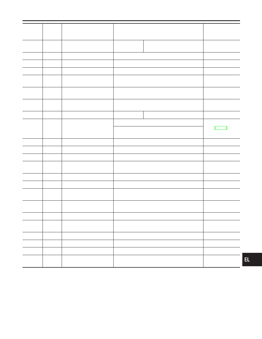
Terminal
No.
Wire
color
Connections
Operated condition
Voltage
(Approximate val-
ues)
23
L/Y
Headlamp switch
Ignition switch
“ON” position
Lighting switch (Except AUTO
,
AUTO position)
12V
,
0V
25
B/R
Ignition key switch (Insert)
Key inserted
,
Key removed from IGN key cylinder
12V
,
0V
26
PU
Ignition switch (ACC)
“ACC” position
12V
27
G
Ignition switch (ON)
Ignition switch is in “ON” position
12V
28
OR
Seat belt buckle switch
Unfastened
,
Fastened (Ignition switch is in “ON”
position)
0V
,
12V
30
R/Y
Ignition keyhole illumination
When doors are unlocked using keyfob (OFF
,
Unlock)
12V
,
0V
31
R
Interior lamp
When doors are locked using keyfob (Unlock
,
lock
with lamp switch in “DOOR” position)
0V
,
12V
32
R/W
Front step lamp
Any door switch
ON (Open)
,
OFF (Closed)
0V
,
12V
33
L
Communication interface
Door lock & unlock switches (Neutral
,
Lock/Unlock)
Front door key cylinder switch LH (Neutral
,
Lock/
Unlock)
37
G/R
Rear window defogger relay
OFF
,
ON (Ignition switch is in “ON” position)
12V
,
0V
38
G/OR
Security indicator
Goes off
,
Illuminates
12V
,
0V
40
B/R
Heated steering relay
OFF
,
ON (Ignition switch is in “ON” position)
12
,
0V
42
BR/Y
Vehicle Security horn relay
When panic alarm is operated using keyfob (ON
,
OFF)
12V
,
0V
43
B
Ground
—
—
46
PU
Power window relay
Retained power operation is operated (ON
,
OFF)
12V
,
0V
47
G/B
LH turn signal lamp
When door lock or unlock is operated using keyfob
(ON
,
OFF)
12V
,
0V
48
G/Y
RH turn signal lamp
When door lock or unlock is operated using keyfob
(ON
,
OFF)
12V
,
0V
49
R/B
Power source (Fuse)
—
12V
50
R/G
Battery saver (Interior lamp)
Battery saver operates
,
Does not operate (ON
,
OFF)
12V
,
0V
51
W/R
Power source (PTC)
—
12V
54
GY
Door lock actuators
Door lock & unlock switch (Free
,
Lock)
0V
,
12V
55
W/B
Driver door lock actuator
Door lock & unlock switch (Free
,
Unlock)
0V
,
12V
56
G/Y
Passenger and rear doors
lock actuator
Door lock & unlock switch (Free
,
Unlock)
0V
,
12V
GI
MA
EM
LC
EC
FE
AT
AX
SU
BR
ST
RS
BT
HA
SC
IDX
SMART ENTRANCE CONTROL UNIT
Smart Entrance Control Unit Inspection Table (Cont’d)
EL-369