Infiniti I35 (A33). Manual - part 372
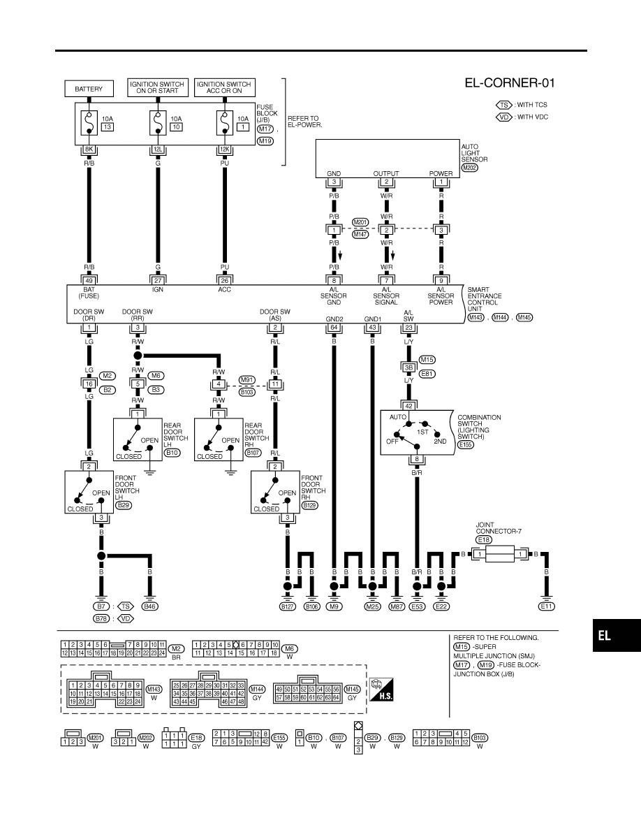
Wiring Diagram — CORNER —
NHEL0270
MEL636R
GI
MA
EM
LC
EC
FE
AT
AX
SU
BR
ST
RS
BT
HA
SC
IDX
CORNERING LAMP
Wiring Diagram — CORNER —
EL-89
|
|
|
Wiring Diagram — CORNER — NHEL0270 MEL636R GI MA EM LC EC FE AT AX SU BR ST RS BT HA SC IDX CORNERING LAMP Wiring Diagram — CORNER — EL-89 |