Infiniti I35 (A33). Manual - part 371
MEL278O
SEL392YB
GI
MA
EM
LC
EC
FE
AT
AX
SU
BR
ST
RS
BT
HA
SC
IDX
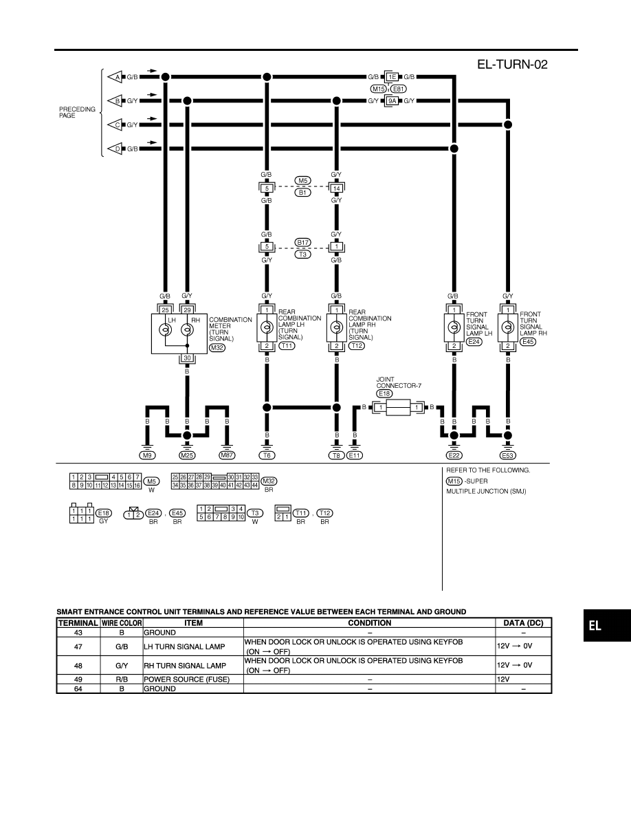
TURN SIGNAL AND HAZARD WARNING LAMPS
Wiring Diagram — TURN — (Cont’d)
EL-85
|
|
|
MEL278O SEL392YB GI MA EM LC EC FE AT AX SU BR ST RS BT HA SC IDX TURN SIGNAL AND HAZARD WARNING LAMPS Wiring Diagram — TURN — (Cont’d) EL-85 |