Infiniti I35 (A33). Manual - part 314
Diagnostic Procedure
NHEC1122
1
INSPECTION START
Do you have CONSULT-II?
Yes or No
Yes
©
GO TO 2.
No
©
GO TO 3.
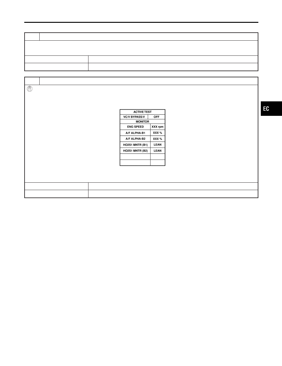
2
CHECK VACUUM CUT VALVE BYPASS VALVE CIRCUIT
With CONSULT-II
1. Turn ignition switch OFF and then ON.
2. Select “VC/V BYPASS/V” in “ACTIVE TEST” mode with CONSULT-II.
3. Touch “ON/OFF” on CONSULT-II screen.
PBIB0157E
4. Make sure that clicking sound is heard from the vacuum cut valve bypass valve.
OK or NG
OK
©
GO TO 7.
NG
©
GO TO 3.
GI
MA
EM
LC
FE
AT
AX
SU
BR
ST
RS
BT
HA
SC
EL
IDX
DTC P1490 VACUUM CUT VALVE BYPASS VALVE
Diagnostic Procedure
EC-597