Infiniti I35 (A33). Manual - part 288
SEF327R
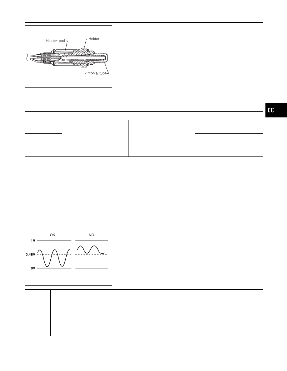
Component Description
NHEC1161
The heated oxygen sensor 2, after three way catalyst (manifold),
monitors the oxygen level in the exhaust gas on each bank.
Even if switching characteristics of the heated oxygen sensor 1 are
shifted, the air fuel ratio is controlled to stoichiometric, by the sig-
nal from the heated oxygen sensor 2.
This sensor is made of ceramic zirconia. The zirconia generates
voltage from approximately 1V in richer conditions to 0V in leaner
conditions.
Under normal conditions the heated oxygen sensor 2 is not used
for engine control operation.
CONSULT-II Reference Value in Data Monitor
Mode
NHEC1162
Specification data are reference values.
MONITOR ITEM
CONDITION
SPECIFICATION
HO2S2 (B1)
HO2S2 (B2)
I
Warm-up condition
I
After keeping engine speed
between 3,500 and 4,000 rpm
for 1 minute and at idle for 1
minute under no load
Revving engine from idle up to
3,000 rpm quickly
0 - 0.3V
+,
Approx. 0.6 - 1.0V
HO2S2 MNTR
(B1)
HO2S2 MNTR
(B2)
LEAN
+,
RICH
SEF972Z
On Board Diagnosis Logic
NHEC1164
The heated oxygen sensor 2 has a much longer switching time
between rich and lean than the heated oxygen sensor 1. The oxy-
gen storage capacity of the three way catalyst causes the longer
switching time. To judge the malfunctions of heated oxygen sensor
2, ECM monitors whether the minimum voltage of sensor is suffi-
ciently low during the various driving condition such as fuel-cut.
DTC No.
Trouble diagnosis
name
DTC Detecting Condition
Possible Cause
P1146
1146
(Bank 1)
P1166
1166
(Bank 2)
Heated oxygen sen-
sor 2 minimum volt-
age monitoring
The minimum voltage from the sensor is not
reached to the specified voltage.
I
Harness or connectors
(The sensor circuit is open or
shorted.)
I
Heated oxygen sensor 2
I
Fuel pressure
I
Injectors
GI
MA
EM
LC
FE
AT
AX
SU
BR
ST
RS
BT
HA
SC
EL
IDX
DTC P1146, P1166 HO2S2
Component Description
EC-493