Infiniti I35 (A33). Manual - part 276
Wiring Diagram
NHEC1261
MEC572D
GI
MA
EM
LC
FE
AT
AX
SU
BR
ST
RS
BT
HA
SC
EL
IDX
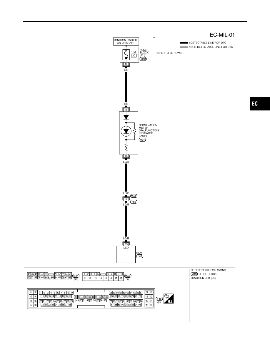
DTC P0650 MIL (CIRCUIT)
Wiring Diagram
EC-445
|
|
|
Wiring Diagram NHEC1261 MEC572D GI MA EM LC FE AT AX SU BR ST RS BT HA SC EL IDX DTC P0650 MIL (CIRCUIT) Wiring Diagram EC-445 |