Infiniti I35 (A33). Manual - part 254


  Index      Infiniti     Infiniti I35 (A33) - service repair manual 2004 year


Search            


Content   ..  252  253  254  255   ..


Infiniti I35 (A33). Manual - part 254


17

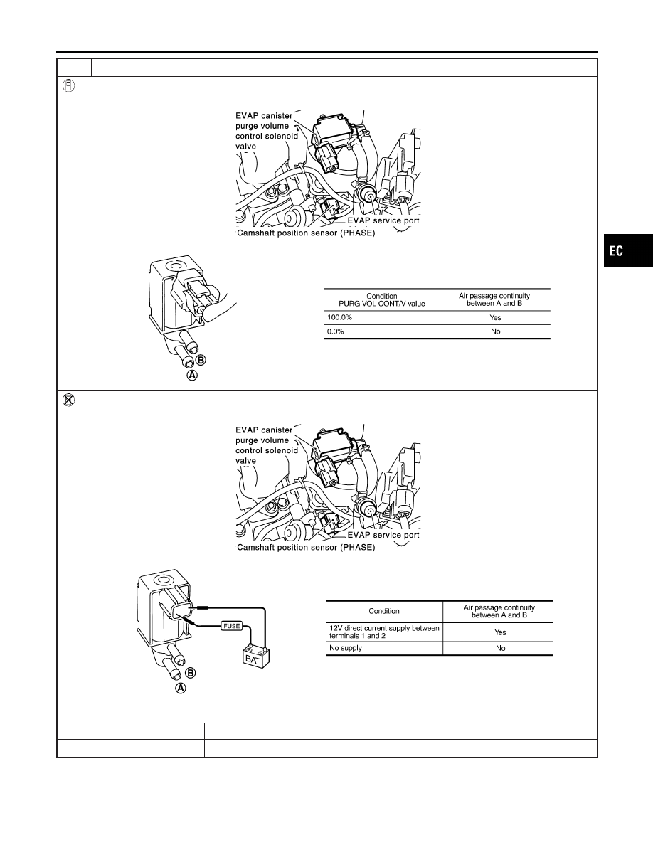
CHECK EVAP CANISTER PURGE VOLUME CONTROL SOLENOID VALVE

With CONSULT-II

Check air passage continuity of EVAP canister purge volume control solenoid valve under the following conditions.

SEC929C

SEF334X

Without CONSULT-II

Check air passage continuity of EVAP canister purge volume control solenoid valve under the following conditions.

SEC929C

SEF335X

OK or NG

OK

©

GO TO 18.

NG

©

Replace EVAP canister purge volume control solenoid valve.

GI

MA

EM

LC

FE

AT

AX

SU

BR

ST

RS

BT

HA

SC

EL

IDX

DTC P0442 EVAP CONTROL SYSTEM

Diagnostic Procedure (Cont’d)

EC-357

18

CHECK FUEL TANK TEMPERATURE SENSOR

1. Remove fuel level sensor unit.
2. Check resistance between fuel level sensor unit and fuel pump terminals 4 and 5 by heating with hot water or heat gun

as shown in the figure.

SEF587X

OK or NG

OK

©

GO TO 19.

NG

©

Replace fuel level sensor unit.

DTC P0442 EVAP CONTROL SYSTEM

Diagnostic Procedure (Cont’d)

EC-358

19

CHECK EVAP CONTROL SYSTEM PRESSURE SENSOR

1. Remove EVAP control system pressure sensor with its harness connector connected.

CAUTION:

Never apply force to the air hole protector of the sensor if equipped.

SEF799W

2. Remove hose from EVAP control system pressure sensor.
3. Turn ignition switch ON.
4. Use pump to apply vacuum and pressure to EVAP control system pressure sensor as shown in figure.

CAUTION:

I

Always calibrate the vacuum pump gauge when using it.

I

Do not apply below −20 kPa (−150 mmHg, −5.91 inHg) or over 20 kPa (150 mmHg, 5.91 inHg) of pressure.

5. Check input voltage between ECM terminal 60 and ground.

SEC908C

MTBL1159

CAUTION:

Discard and EVAP control system pressure sensor which has been dropped from a height of more than 0.5 m
(19.7 in) onto a hard surface such as a concrete floor; use a new one.

OK or NG

OK

©

GO TO 20.

NG

©

Replace EVAP control system pressure sensor.

20

CHECK EVAP PURGE LINE

Check EVAP purge line (pipe, rubber tube, fuel tank and EVAP canister) for cracks or improper connection.
Refer to “Evaporative Emission System”, EC-37.

OK or NG

OK

©

GO TO 21.

NG

©

Repair or reconnect the hose.

GI

MA

EM

LC

FE

AT

AX

SU

BR

ST

RS

BT

HA

SC

EL

IDX

DTC P0442 EVAP CONTROL SYSTEM

Diagnostic Procedure (Cont’d)

EC-359

21

CLEAN EVAP PURGE LINE

Clean EVAP purge line (pipe and rubber tube) using air blower.

©

GO TO 22.

22

CHECK REFUELING EVAP VAPOR LINE

Check refueling EVAP vapor line between EVAP canister and fuel tank for clogging, kink, looseness and improper connec-
tion. For location, refer to “ON BOARD REFUELING VAPOR RECOVERY (ORVR)”, EC-43.

OK or NG

OK

©

GO TO 23.

NG

©

Repair or replace hoses and tubes.

23

CHECK SIGNAL LINE AND RECIRCULATION LINE

Check signal line and recirculation line between filler neck tube and fuel tank for clogging, kink, cracks, looseness and
improper connection.

OK or NG

OK

©

GO TO 24.

NG

©

Repair or replace hoses, tubes or filler neck tube.

24

CHECK REFUELING CONTROL VALVE

1. Remove fuel filler cap.
2. Check air continuity between hose ends A and B.

Blow air into the hose end B. Air should flow freely into the fuel tank.

3. Blow air into hose end A and check there is no leakage.
4. Apply pressure to both hose ends A and B [20 kPa (150 mmHg, 5.91 inHg)] using a pressure pump and a suitable

3-way connector. Check that there is no leakage.

SEF830X

OK or NG

OK

©

GO TO 25.

NG

©

Replace refueling control valve with fuel tank.

DTC P0442 EVAP CONTROL SYSTEM

Diagnostic Procedure (Cont’d)

EC-360


Content   ..  252  253  254  255   ..