Infiniti I35 (A33). Manual - part 248


  Index      Infiniti     Infiniti I35 (A33) - service repair manual 2004 year


Search            


Content   ..  246  247  248  249   ..


Infiniti I35 (A33). Manual - part 248


“COOLANTEMP/S” indication on CONSULT-II.

d)

When “COOLANTEMP/S” indication reaches to 70°C (158°F),
go to step 3.

10) Select “SELF-DIAG RESULTS” mode with CONSULT-II.
11) Confirm that the 1st trip DTC is not detected.

If the 1st trip DTC is detected, go to “Diagnostic Procedure”,
EC-334.

SEC902C

SEC903C

Overall Function Check

NHEC0953

Use this procedure to check the overall function of the three way
catalyst (manifold). During this check, a 1st trip DTC might not be
confirmed.

CAUTION:

Always drive vehicle at a safe speed.

WITH GST

NHEC0953S01

1)

Start engine and warm it up to the normal operating tempera-
ture.

2)

Turn ignition switch OFF and wait at least 10 seconds.

3)

Start engine and keep the engine speed between 3,500 and
4,000 rpm for at least 1 minute under no load.

4)

Let engine idle for 1 minute.
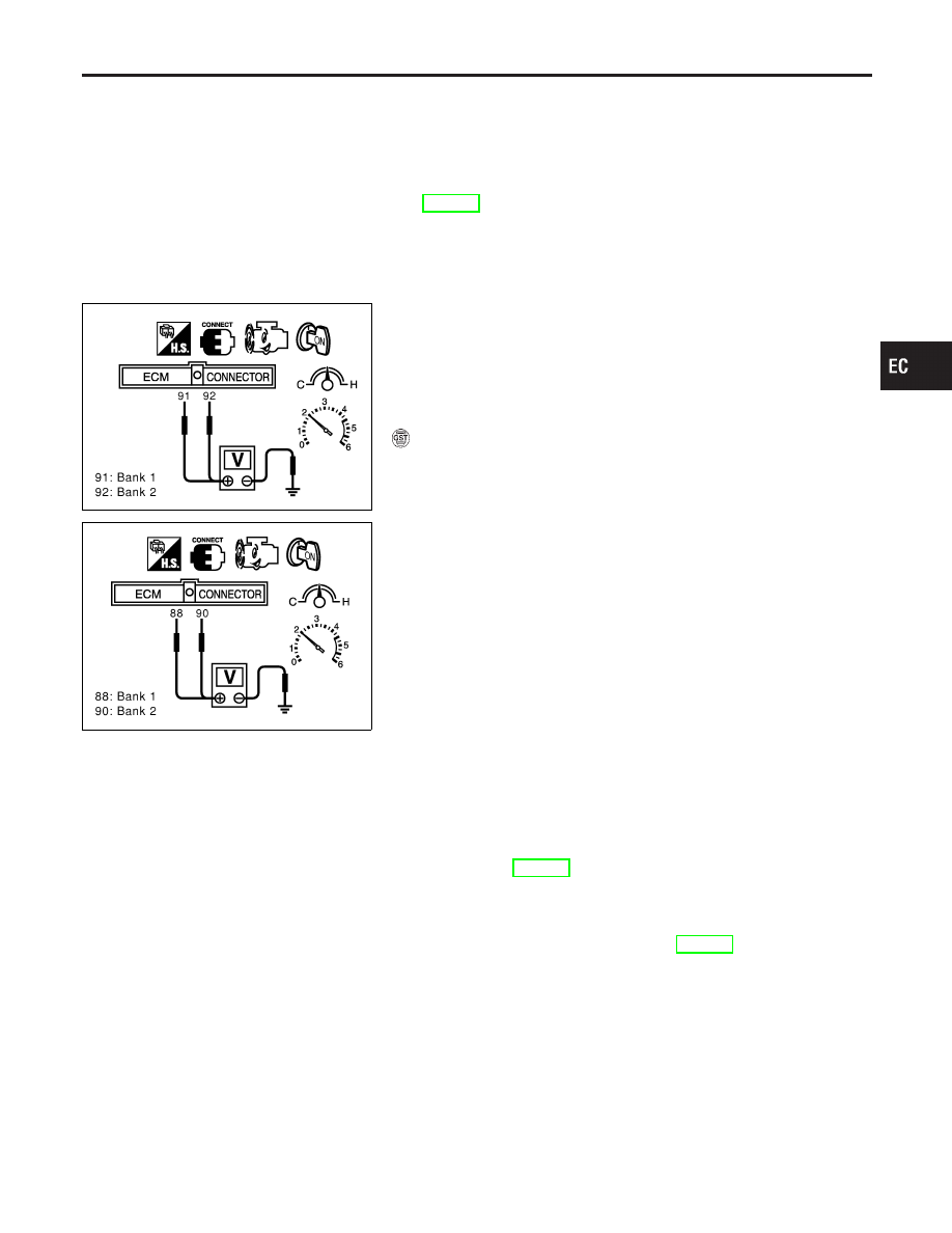
5)

Set voltmeters probes between ECM terminals 91 [heated oxy-
gen sensor 1 bank 1 signal], 92 [heated oxygen sensor 1 bank
2 signal] and ground, and ECM terminals 88 [heated oxygen
sensor 2 bank 1 signal], 90 [heated oxygen sensor 2 bank 2
signal] and ground.

6)

Keep engine speed at 2,000 rpm constant under no load.

7)

Make sure that the voltage switching frequency (high & low)
between ECM terminals 88 and ground, or 90 and ground is
very less than that of ECM terminals 91 and ground, or 91 and
engine ground.
Switching frequency ratio = A/B
A: Heated oxygen sensor 2 voltage switching frequency
B: Heated oxygen sensor 1 voltage switching frequency
This ratio should be less than 0.75.
If the ratio is greater than above, it means three way catalyst
(manifold) does not operate properly. Go to “Diagnostic
Procedure”, EC-334.

NOTE:
If the voltage at terminal 92 or 91 does not switch periodically more
than 5 times within 10 seconds at step 5, perform trouble diagno-
sis for “DTC P0133, P0153” first. (See EC-235.)

GI

MA

EM

LC

FE

AT

AX

SU

BR

ST

RS

BT

HA

SC

EL

IDX

DTC P0420, P0430 THREE WAY CATALYST FUNCTION

DTC Confirmation Procedure (Cont’d)

EC-333

Diagnostic Procedure

=NHEC0954

1

CHECK EXHAUST SYSTEM

Visually check exhaust tubes and muffler for dent.

OK or NG

OK

©

GO TO 2.

NG

©

Repair or replace.

2

CHECK EXHAUST GAS LEAK

1. Start engine and run it at idle.
2. Listen for an exhaust gas leak before the three way catalyst (manifold).

SEC502D

OK or NG

OK

©

GO TO 3.

NG

©

Repair or replace.

3

CHECK INTAKE AIR LEAK

Listen for an intake air leak after the mass air flow sensor.

OK or NG

OK

©

GO TO 4.

NG

©

Repair or replace.

4

CHECK IGNITION TIMING

Check the following items. Refer to “Basic Inspection”, EC-120.

MTBL1839

OK or NG

OK

©

GO TO 5.

NG

©

Follow the “Basic Inspection”.

DTC P0420, P0430 THREE WAY CATALYST FUNCTION

Diagnostic Procedure

EC-334

5

CHECK INJECTORS

1. Refer to WIRING DIAGRAM for Injectors, EC-697.
2. Stop engine and then turn ignition switch ON.
3. Check voltage between ECM terminals 1, 2, 3, 11, 12, 13 and ground with CONSULT-II or tester.

SEC395D

Voltage: Battery voltage

OK or NG

OK

©

GO TO 6.

NG

©

Perform “Diagnostic Procedure”, “INJECTOR”, EC-698.

6

CHECK IGNITION SPARK

1. Turn ignition switch OFF.
2. Remove ignition coil assembly from rocker cover.
3. Connect a known good spark plug to the ignition wire.
4. Disconnect all injector harness connectors.
5. Place end of spark plug against a suitable ground and crank engine.
6. Check for spark.

SEF575Q

OK or NG

OK

©

GO TO 7.

NG

©

Check ignition coil with power transistor and their circuit. Refer to EC-685.

GI

MA

EM

LC

FE

AT

AX

SU

BR

ST

RS

BT

HA

SC

EL

IDX

DTC P0420, P0430 THREE WAY CATALYST FUNCTION

Diagnostic Procedure (Cont’d)

EC-335

7

CHECK INJECTOR

1. Turn ignition switch OFF.
2. Remove injector assembly.

Refer to EC-56.
Keep fuel hose and all injectors connected to injector gallery.

3. Disconnect all ignition coil harness connectors.
4. Reconnect injector harness connectors.
5. Turn ignition switch ON.

Make sure fuel does not drip from injector.

OK or NG

OK (Does not drip.)

©

GO TO 8.

NG (Drips.)

©

Replace the injector(s) from which fuel is dripping.

8

CHECK INTERMITTENT INCIDENT

Refer to “TROUBLE DIAGNOSIS FOR INTERMITTENT INCIDENT”, EC-152.

Trouble is fixed.

©

INSPECTION END

Trouble is not fixed.

©

Replace three way catalyst (manifold).

DTC P0420, P0430 THREE WAY CATALYST FUNCTION

Diagnostic Procedure (Cont’d)

EC-336


Content   ..  246  247  248  249   ..