Infiniti I35 (A33). Manual - part 246
Wiring Diagram
NHEC0949
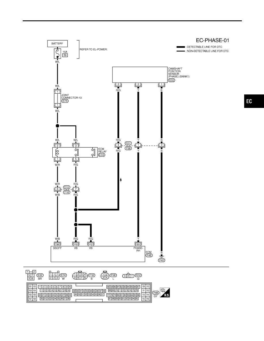
BANK 1
NHEC0949S01
MEC573D
GI
MA
EM
LC
FE
AT
AX
SU
BR
ST
RS
BT
HA
SC
EL
IDX
DTC P0340, P0345 CMP SENSOR (PHASE)
Wiring Diagram
EC-325
|
|
|
Wiring Diagram NHEC0949 BANK 1 NHEC0949S01 MEC573D GI MA EM LC FE AT AX SU BR ST RS BT HA SC EL IDX DTC P0340, P0345 CMP SENSOR (PHASE) Wiring Diagram EC-325 |