Infiniti I35 (A33). Manual - part 232


  Index      Infiniti     Infiniti I35 (A33) - service repair manual 2004 year


Search            


Content   ..  230  231  232  233   ..


Infiniti I35 (A33). Manual - part 232


Diagnostic Procedure

NHEC0911

1

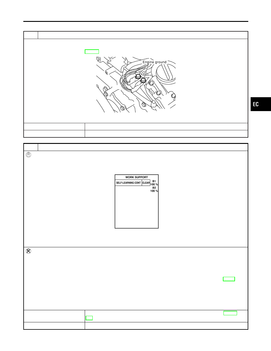
CHECK GROUND CONNECTIONS

1. Turn ignition switch OFF.
2. Loosen and retighten two engine ground screws.

Refer to “Ground Inspection”, EC-160.

SEC047D

OK or NG

OK

©

GO TO 2.

NG

©

Repair or replace ground connections.

2

CLEAR THE SELF-LEARNING DATA

With CONSULT-II

1. Start engine and warm it up to normal operating temperature.
2. Select “SELF-LEARNING CONT” in “WORK SUPPORT” mode with CONSULT-II.
3. Clear the self-learning control coefficient by touching “CLEAR”.

SEF968Y

4. Run engine for at least 10 minutes at idle speed.

Is the 1st trip DTC P0171, P0172, P0174 or P0175 detected?
Is it difficult to start engine?

Without CONSULT-II

1. Start engine and warm it up to normal operating temperature.
2. Turn ignition switch OFF.
3. Disconnect mass air flow sensor harness connector, and restart and run engine for at least 5 seconds at idle speed.
4. Stop engine and reconnect mass air flow sensor harness connector.
5. Make sure DTC No. P0102 is displayed.
6. Erase the DTC memory. Refer to “HOW TO ERASE EMISSION-RELATED DIAGNOSTIC INFORMATION”, EC-88.
7. Make sure DTC No. P0000 is displayed.
8. Run engine for at least 10 minutes at idle speed.

Is the 1st trip DTC P0171, P0172, P0174 or P0175 detected?
Is it difficult to start engine?

Yes or No

Yes

©

Perform trouble diagnosis for DTC P0171, P0174 or P0172, P0175. Refer to EC-273,
281.

No

©

GO TO 3.

GI

MA

EM

LC

FE

AT

AX

SU

BR

ST

RS

BT

HA

SC

EL

IDX

DTC P0139, P0159 HO2S2

Diagnostic Procedure

EC-269

3

CHECK HO2S2 INPUT SIGNAL CIRCUIT FOR OPEN AND SHORT

1. Turn ignition switch OFF.
2. Disconnect corresponding heated oxygen sensor 2 harness connector.

SEC134D

3. Disconnect ECM harness connector.
4. Check harness continuity between ECM terminal and HO2S2 terminal as follows.

Refer to Wiring Diagram.

MTBL1152

Continuity should exist.

5. Check harness continuity between ECM terminal or HO2S2 terminal and ground as follows.

Refer to Wiring Diagram.

MTBL1153

Continuity should not exist.

6. Also check harness for short to power.

OK or NG

OK

©

GO TO 4.

NG

©

Repair open circuit or short to ground or short to power in harness or connectors.

4

CHECK HO2S2 GROUND CIRCUIT FOR OPEN AND SHORT

1. Check harness continuity between HO2S2 terminal 4 and ground.

Refer to Wiring Diagram.

Continuity should exist.

2. Also check harness for short to power.

OK or NG

OK (With CONSULT-II)

©

GO TO 6.

OK (Without CONSULT-
II)

©

GO TO 7.

NG

©

GO TO 5.

DTC P0139, P0159 HO2S2

Diagnostic Procedure (Cont’d)

EC-270

5

DETECT MALFUNCTIONING PART

Check the following.

I

Joint connector-18

I

Harness for open and short between HO2S2 and ground

©

Repair open circuit or short to power in harness or connectors.

6

CHECK HEATED OXYGEN SENSOR 2

With CONSULT-II

1. Start engine and warm it up to the normal operating temperature.
2. Turn ignition switch OFF and wait at least 10 seconds.
3. Start engine and keep the engine speed between 3,500 and 4,000 rpm for at least 1 minute under no load.
4. Let engine idle for 1 minute.
5. Select “FUEL INJECTION” in “ACTIVE TEST” mode, and select “HO2S2 (B1)/(B2)” as the monitor item with CONSULT-

II.

6. Check “HO2S2 (B1)/(B2)” at idle speed when adjusting “FUEL INJECTION” to

±

25%.

SEF066YA

“HO2S2 (B1)/(B2)” should be above 0.63V at least once when the “FUEL INJECTION” is +25%.
“HO2S2 (B1)/(B2)” should be below 0.48V at least once when the “FUEL INJECTION” is −25%.

CAUTION:

I

Discard any heated oxygen sensor which has been dropped from a height of more than 0.5 m (19.7 in) onto
a hard surface such as a concrete floor; use a new one.

I

Before installing new oxygen sensor, clean exhaust system threads using Oxygen Sensor Thread Cleaner
tool J-43897-18 or J-43897-12 and approved anti-seize lubricant.

OK or NG

OK

©

GO TO 9.

NG

©

Replace malfunctioning heated oxygen sensor 2.

GI

MA

EM

LC

FE

AT

AX

SU

BR

ST

RS

BT

HA

SC

EL

IDX

DTC P0139, P0159 HO2S2

Diagnostic Procedure (Cont’d)

EC-271

7

CHECK HEATED OXYGEN SENSOR 2-I

Without CONSULT-II

1. Start engine and warm it up to the normal operating temperature.
2. Turn ignition switch OFF and wait at least 10 seconds.
3. Start engine and keep the engine speed at between 3,500 to 4,000 rpm for at least 1 minute under no load.
4. Let engine idle for 1 minute.
5. Set voltmeter probes between ECM terminal 88 (HO2S2 bank 1 signal) or 90 (HO2S2 bank 2 signal) and ground.
6. Check the voltage when revving up to 4,000 rpm under no load at least 10 times.

(Depress and release accelerator pedal as soon as possible.)

SEC114D

OK or NG

OK

©

GO TO 9.

NG

©

GO TO 8.

8

CHECK HEATED OXYGEN SENSOR 2-II

Idle vehicle for 10 minutes, then check voltage between the same terminals as in Test No. 7; or check voltage when coast-
ing from 80 km/h (50 MPH) in D position with “OD” OFF.
The voltage should go below 0.48V at least once during this procedure.

CAUTION:

I

Discard any heated oxygen sensor which has been dropped from a height of more than 0.5 m (19.7 in) onto a
hard surface such as a concrete floor; use a new one.

I

Before installing new oxygen sensor, clean exhaust system threads using Oxygen Sensor Thread Cleaner tool
J-43897-18 or J-43897-12 and approved anti-seize lubricant.

OK or NG

OK

©

GO TO 9.

NG

©

Replace malfunctioning heated oxygen sensor 2.

9

CHECK INTERMITTENT INCIDENT

Refer to “TROUBLE DIAGNOSIS FOR INTERMITTENT INCIDENT”, EC-152.

©

INSPECTION END

DTC P0139, P0159 HO2S2

Diagnostic Procedure (Cont’d)

EC-272


Content   ..  230  231  232  233   ..