Infiniti I35 (A33). Manual - part 228


  Index      Infiniti     Infiniti I35 (A33) - service repair manual 2004 year


Search            


Content   ..  226  227  228  229   ..


Infiniti I35 (A33). Manual - part 228


2

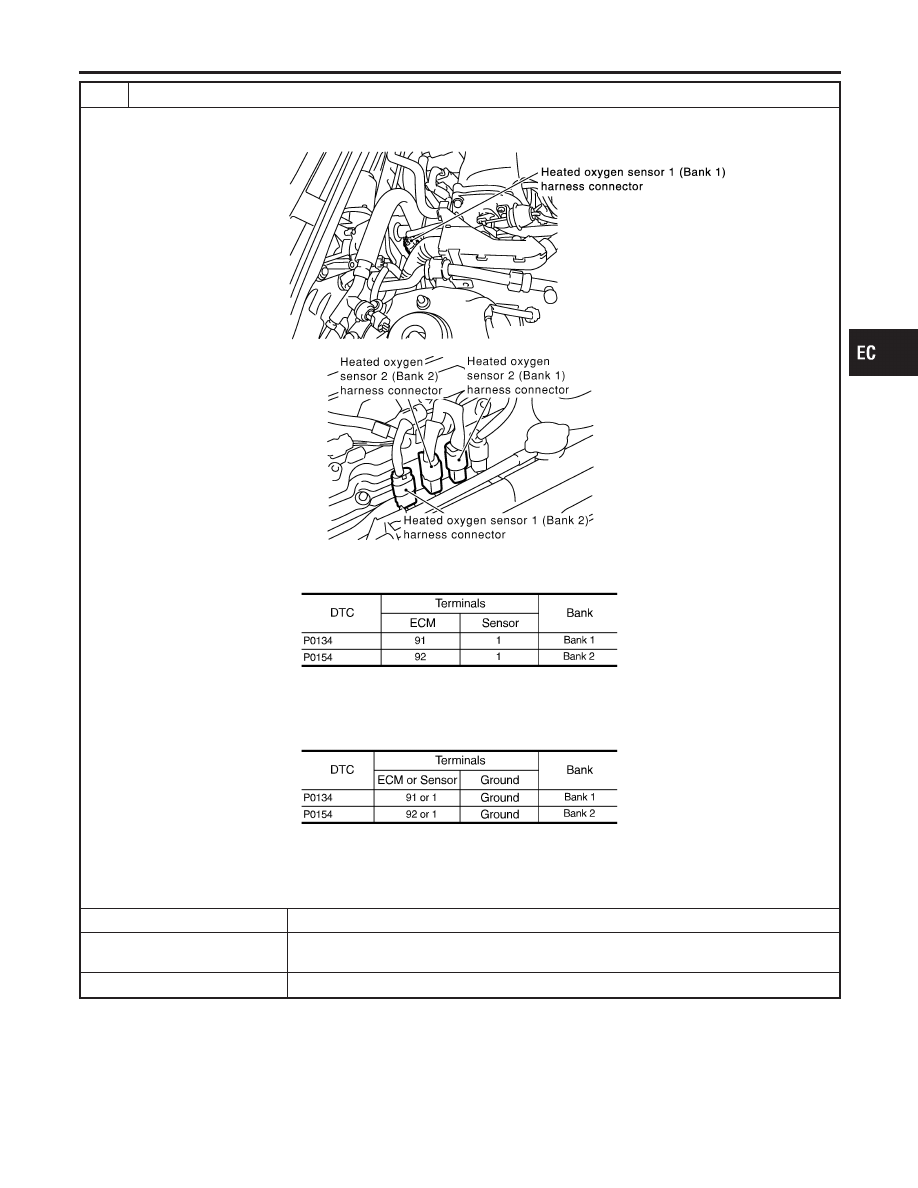
CHECK HO2S1 INPUT SIGNAL CIRCUIT FOR OPEN AND SHORT

1. Disconnect ECM harness connector.
2. Disconnect heated oxygen sensor 1 harness connector.

SEC099D

SEC134D

3. Check harness continuity between ECM terminal and HO2S1 terminal as follows.

Refer to Wiring Diagram.

MTBL1148

Continuity should exist.

4. Check harness continuity between ECM terminal or HO2S1 terminal and ground as follows.

Refer to Wiring Diagram.

MTBL1149

Continuity should not exist.

5. Also check harness for short to power.

OK or NG

OK (With CONSULT-II)

©

GO TO 3.

OK (Without CONSULT-
II)

©

GO TO 4.

NG

©

Repair open circuit or short to ground or short to power in harness or connectors.

GI

MA

EM

LC

FE

AT

AX

SU

BR

ST

RS

BT

HA

SC

EL

IDX

DTC P0134, P0154 HO2S1

Diagnostic Procedure (Cont’d)

EC-253

3

CHECK HEATED OXYGEN SENSOR 1

With CONSULT-II

1. Start engine and warm it up to normal operating temperature.
2. Select “MANU TRIG” and adjust “TRIGGER POINT” to 100% in “DATA MONITOR” mode with CONSULT-II.
3. Select “HO2S1 (B1)/(B2)” and “HO2S1 MNTR (B1)/(B2)”.
4. Hold engine speed at 2,000 rpm under no load during the following steps.
5. Touch “RECORD” on CONSULT-II screen.

SEF967Y

6. Check the following.

I

“HO2S1 MNTR (B1)/(B2)” in “DATA MONITOR” mode changes from “RICH” to “LEAN” to “RICH” more than 5 times in
10 seconds.
5 times (cycles) are counted as shown below.

SEF647Y

I

“HO2S1 (B1)/(B2)” voltage goes above 0.6V at least once.

I

“HO2S1 (B1)/(B2)” voltage goes below 0.3V at least once.

I

“HO2S1 (B1)/(B2)” voltage never exceeds 1.0V.

SEF648Y

CAUTION:

I

Discard any heated oxygen sensor which has been dropped from a height of more than 0.5 m (19.7 in) onto a
hard surface such as a concrete floor; use a new one.

I

Before installing new oxygen sensor, clean exhaust system threads using Oxygen Sensor Thread Cleaner tool
J-43897-18 or J-43897-12 and approved anti-seize lubricant.

OK or NG

OK

©

GO TO 5.

NG

©

Replace malfunctioning heated oxygen sensor 1.

DTC P0134, P0154 HO2S1

Diagnostic Procedure (Cont’d)

EC-254

4

CHECK HEATED OXYGEN SENSOR 1

Without CONSULT-II

1. Start engine and warm it up to normal operating temperature.
2. Set voltmeter probes between ECM terminal 91 (HO2S1 bank 1 signal) or 92 (HO2S1 bank 2 signal) and ground.
3. Check the following with engine speed held at 2,000 rpm constant under no load.

SEC109D

CAUTION:

I

Discard any heated oxygen sensor which has been dropped from a height of more than 0.5 m (19.7 in) onto a
hard surface such as a concrete floor; use a new one.

I

Before installing new oxygen sensor, clean exhaust system threads using Oxygen Sensor Thread Cleaner tool
J-43897-18 or J-43897-12 and approved anti-seize lubricant.

OK or NG

OK

©

GO TO 5.

NG

©

Replace malfunctioning heated oxygen sensor 1.

5

CHECK INTERMITTENT INCIDENT

Refer to “TROUBLE DIAGNOSIS FOR INTERMITTENT INCIDENT”, EC-152.

©

INSPECTION END

GI

MA

EM

LC

FE

AT

AX

SU

BR

ST

RS

BT

HA

SC

EL

IDX

DTC P0134, P0154 HO2S1

Diagnostic Procedure (Cont’d)

EC-255

SEF327R

Component Description

NHEC0896

The heated oxygen sensor 2, after three way catalyst, monitors the
oxygen level in the exhaust gas on each bank.
Even if switching characteristics of the heated oxygen sensor 1 are
shifted, the air fuel ratio is controlled to stoichiometric, by the sig-
nal from the heated oxygen sensor 2.
This sensor is made of ceramic zirconia. The zirconia generates
voltage from approximately 1V in richer conditions to 0V in leaner
conditions.
Under normal conditions the heated oxygen sensor 2 is not used
for engine control operation.

CONSULT-II Reference Value in Data Monitor
Mode

NHEC0897

Specification data are reference values.

MONITOR ITEM

CONDITION

SPECIFICATION

HO2S2 (B1)
HO2S2 (B2)

I

Warm-up condition

I

After keeping engine speed
between 3,500 and 4,000 rpm
for 1 minute and at idle for 1
minute under no load

Revving engine from idle up to
3,000 rpm quickly

0 - 0.3V

+,

Approx. 0.6 - 1.0V

HO2S2 MNTR
(B1)
HO2S2 MNTR
(B2)

LEAN

+,

RICH

SEF305UA

On Board Diagnosis Logic

NHEC0899

The heated oxygen sensor 2 has a much longer switching time
between rich and lean than the heated oxygen sensor 1. The oxy-
gen storage capacity before the three way catalyst causes the
longer switching time. To judge the malfunctions of heated oxygen
sensor 2, ECM monitors whether the voltage is unusually high
during the various driving condition such as fuel-cut.

DTC No.

Trouble diagnosis

name

DTC Detecting Condition

Possible Cause

P0138
0138
(Bank 1)
P0158
0158
(Bank 2)

Heated oxygen sen-
sor 2 circuit high volt-
age

An excessively high voltage from the sensor is
sent to ECM.

I

Harness or connectors
(The sensor circuit is open or
shorted.)

I

Heated oxygen sensor 2

DTC P0138, P0158 HO2S2

Component Description

EC-256


Content   ..  226  227  228  229   ..