Infiniti I35 (A33). Manual - part 224
SEF338Z
SEF339Z
SEF658Y
WITH CONSULT-II
NHEC0884S01
1)
Start engine and warm it up to normal operating temperature.
2)
Stop engine and wait at least 5 seconds.
3)
Turn ignition switch “ON” and select “HO2S1 (B1)/(B2) P0133/
P0153” of “HO2S1” in “DTC WORK SUPPORT” mode with
CONSULT-II.
4)
Touch “START”.
5)
Start engine and let it idle for at least 3 minutes.
NOTE:
Never raise engine speed above 3,600 rpm after this step. If
the engine speed limit is exceeded, return to step 5.
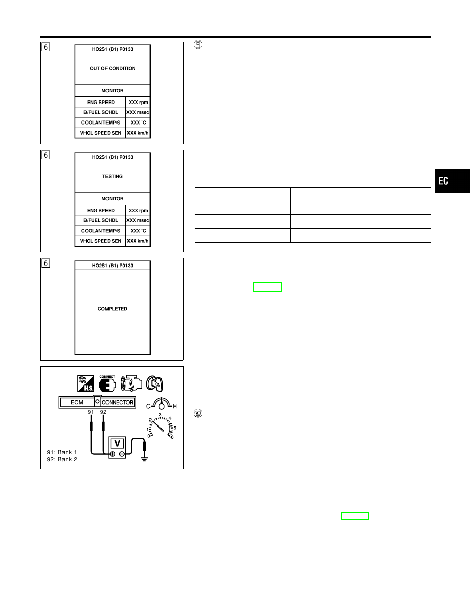
6)
When the following conditions are met, “TESTING” will be dis-
played on the CONSULT-II screen. Maintain the conditions
continuously until “TESTING” changes to “COMPLETED”. (It
will take approximately 40 to 50 seconds.)
ENG SPEED
1,200 - 3,100 rpm
Vehicle speed
More than 80 km/h (50 MPH)
B/FUEL SCHDL
2.5 - 12 msec
Selector lever
Suitable position
If “TESTING” is not displayed after 5 minutes, retry from
step 2.
7)
Make sure that “OK” is displayed after touching “SELF-DIAG
RESULTS”.
If
“NG”
is
displayed,
refer
to
“Diagnostic
Procedure”, EC-240.
SEC902C
Overall Function Check
NHEC0885
Use this procedure to check the overall function of the heated oxy-
gen sensor 1 circuit. During this check, a 1st trip DTC might not be
confirmed.
WITH GST
NHEC0885S01
1)
Start engine and warm it up to normal operating temperature.
2)
Set voltmeter probes between ECM terminal 91 (HO2S1 bank
1 signal) or 92 (HO2S1 bank 2 signal) and ground.
3)
Check the following with engine speed held at 2,000 rpm con-
stant under no load.
I
The voltage fluctuates between 0 to 0.3V and 0.6 to 1.0V more
than 5 times within 10 seconds.
1 time: 0 - 0.3V
→
0.6 - 1.0V
→
0 - 0.3V
2 times: 0 - 0.3V
→
0.6 - 1.0V
→
0 - 0.3V
→
0.6 - 1.0V
→
0
- 0.3V
4)
If NG, go to “Diagnostic Procedure”, EC-240.
GI
MA
EM
LC
FE
AT
AX
SU
BR
ST
RS
BT
HA
SC
EL
IDX
DTC P0133, P0153 HO2S1
DTC Confirmation Procedure (Cont’d)
EC-237