Infiniti I35 (A33). Manual - part 221


  Index      Infiniti     Infiniti I35 (A33) - service repair manual 2004 year


Search            


Content   ..  219  220  221  222   ..


Infiniti I35 (A33). Manual - part 221


Diagnostic Procedure

NHEC1292

1

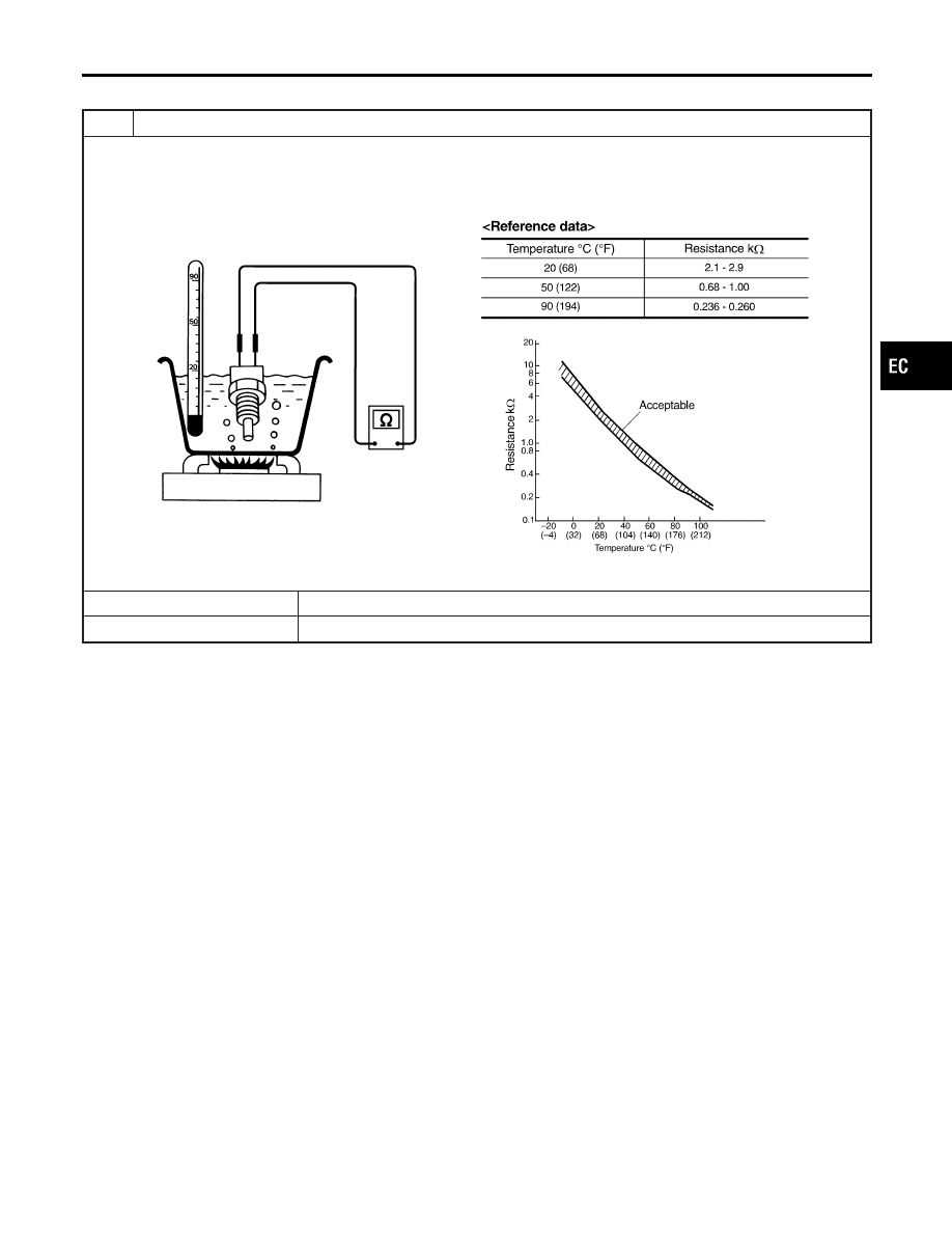
CHECK ENGINE COOLANT TEMPERATURE SENSOR

1. Turn ignition switch OFF.
2. Remove engine coolant temperature sensor.
3. Check resistance between engine coolant temperature sensor terminals under the following conditions.

SEF304X

OK or NG

OK

©

INSPECTION END

NG

©

Replace engine coolant temperature sensor.

GI

MA

EM

LC

FE

AT

AX

SU

BR

ST

RS

BT

HA

SC

EL

IDX

DTC P0128 THERMOSTAT FUNCTION

Diagnostic Procedure

EC-225

SEF463R

SEF288D

Component Description

NHEC0873

The heated oxygen sensor 1 is placed into the front tube. It detects
the amount of oxygen in the exhaust gas compared to the outside
air. The heated oxygen sensor 1 has a closed-end tube made of
ceramic zirconia. The zirconia generates voltage from approxi-
mately 1V in richer conditions to 0V in leaner conditions. The
heated oxygen sensor 1 signal is sent to the ECM. The ECM
adjusts the injection pulse duration to achieve the ideal air-fuel
ratio. The ideal air-fuel ratio occurs near the radical change from
1V to 0V.

CONSULT-II Reference Value in Data Monitor
Mode

NHEC0874

Specification data are reference values.

MONITOR ITEM

CONDITION

SPECIFICATION

HO2S1 (B1)
HO2S1 (B2)

I

Engine: After warming up

Maintaining engine speed at 2,000
rpm

0 - 0.3V

+,

Approx. 0.6 - 1.0V

HO2S1 MNTR
(B1)
HO2S1 MNTR
(B2)

LEAN

+,

RICH

Changes more than 5 times during
10 seconds.

SEF301UA

On Board Diagnosis Logic

NHEC0876

To judge the malfunction, the diagnosis checks that the heated
oxygen sensor 1 output is not inordinately high.

DTC P0132, P0152 HO2S1

Component Description

EC-226

DTC No.

Trouble diagnosis

name

DTC Detecting Condition

Possible Cause

P0132
0132
(Bank 1)
P0152
0152
(Bank 2)

Heated oxygen sen-
sor 1 circuit high volt-
age

An excessively high voltage from the sensor is
sent to ECM.

I

Harness or connectors
(The sensor circuit is open or
shorted.)

I

Heated oxygen sensor 1

SEF174Y

DTC Confirmation Procedure

NHEC0877

NOTE:
If DTC Confirmation Procedure has been previously conducted,
always turn ignition switch OFF and wait at least 10 seconds before
conducting the next test.

WITH CONSULT-II

NHEC0877S01

1)

Start engine and warm it up to normal operating temperature.

2)

Turn ignition switch OFF and wait at least 10 seconds.

3)

Turn ignition switch ON.

4)

Select “DATA MONITOR” mode with CONSULT-II.

5)

Restart engine and let it idle for 25 seconds.

6)

If 1st trip DTC is detected, go to “Diagnostic Procedure”,
EC-230.

WITH GST

NHEC0877S02

Follow the procedure “WITH CONSULT-II” above.

GI

MA

EM

LC

FE

AT

AX

SU

BR

ST

RS

BT

HA

SC

EL

IDX

DTC P0132, P0152 HO2S1

On Board Diagnosis Logic (Cont’d)

EC-227

Wiring Diagram

NHEC0878

BANK 1

NHEC0878S01

MEC537D

SEC107D

DTC P0132, P0152 HO2S1

Wiring Diagram

EC-228


Content   ..  219  220  221  222   ..