Infiniti I35 (A33). Manual - part 220
SEC266C
SEF012P
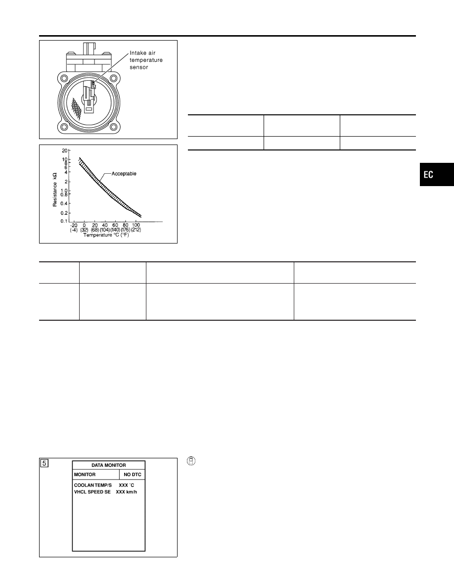
Component Description
NHEC0767
The intake air temperature sensor is mounted to the air duct hous-
ing. The sensor detects intake air temperature and transmits a sig-
nal to the ECM.
The temperature sensing unit uses a thermistor which is sensitive
to the change in temperature. Electrical resistance of the thermistor
decreases in response to the temperature rise.
<Reference data>
Intake air
temperature
°C (°F)
Voltage*
V
Resistance
k
Ω
25 (77)
3.32
1.9 - 2.1
*: This data is reference value and is measured between ECM terminal 66 (Intake
air temperature sensor) and body ground.
CAUTION:
Do not use ECM ground terminals when measuring input/
output voltage. Doing so may result in damage to the ECM’s
transistor. Use a ground other than ECM terminals, such as
the ground.
On Board Diagnosis Logic
NHEC0768
DTC No.
Trouble diagnosis
name
DTC Detecting Condition
Possible Cause
P0127
0127
Intake air temperature
too high
Rationally incorrect voltage from the sensor is sent
to ECM, compared with the voltage signal from
engine coolant temperature sensor.
I
Harness or connectors
(The sensor circuit is open or
shorted.)
I
Intake air temperature sensor
DTC Confirmation Procedure
NHEC0770
NOTE:
If DTC Confirmation Procedure has been previously conducted,
always turn ignition switch OFF and wait at least 10 seconds before
conducting the next test.
CAUTION:
Always drive vehicle at a safe speed.
TESTING CONDITION:
This test may be conducted with the drive wheels lifted in the
shop or by driving the vehicle. If a road test is expected to be
easier, it is unnecessary to lift the vehicle.
SEF176Y
WITH CONSULT-II
NHEC0770S03
1)
Wait until engine coolant temperature is less than 90°C
(194°F).
a)
Turn ignition switch ON.
b)
Select “DATA MONITOR” mode with CONSULT-II.
c)
Check the engine coolant temperature.
d)
If the engine coolant temperature is not less than 90°C
(194°F), turn ignition switch OFF and cool down engine.
I
Perform the following steps before engine coolant temperature
is above 90°C (194°F).
2)
Turn ignition switch ON.
GI
MA
EM
LC
FE
AT
AX
SU
BR
ST
RS
BT
HA
SC
EL
IDX
DTC P0127 IAT SENSOR
Component Description
EC-221