Infiniti I35 (A33). Manual - part 219
5
CHECK THROTTLE POSITION SENSOR 2 INPUT SIGNAL CIRCUIT FOR OPEN AND SHORT
1. Check harness continuity between ECM terminal 84 and electric throttle control actuator terminal 2.
Refer to Wiring Diagram.
Continuity should exist.
2. Also check harness for short to ground and short to power.
OK or NG
OK
©
GO TO 6.
NG
©
Repair open circuit or short to ground or short to power in harness or connectors.
6
CHECK THROTTLE POSITION SENSOR
Refer to “Component Inspection”, EC-217.
OK or NG
OK
©
GO TO 8.
NG
©
GO TO 7.
7
REPLACE ELECTRIC THROTTLE CONTROL ACTUATOR
1. Replace the electric throttle control actuator.
2. Perform “Throttle Valve Closed Position Learning”, EC-70.
3. Perform “Idle Air Volume Learning”, EC-70.
©
INSPECTION END
8
CHECK INTERMITTENT INCIDENT
Refer to “TROUBLE DIAGNOSIS FOR INTERMITTENT INCIDENT”, EC-152.
©
INSPECTION END
PBIB0968E
Component Inspection
NHEC1339
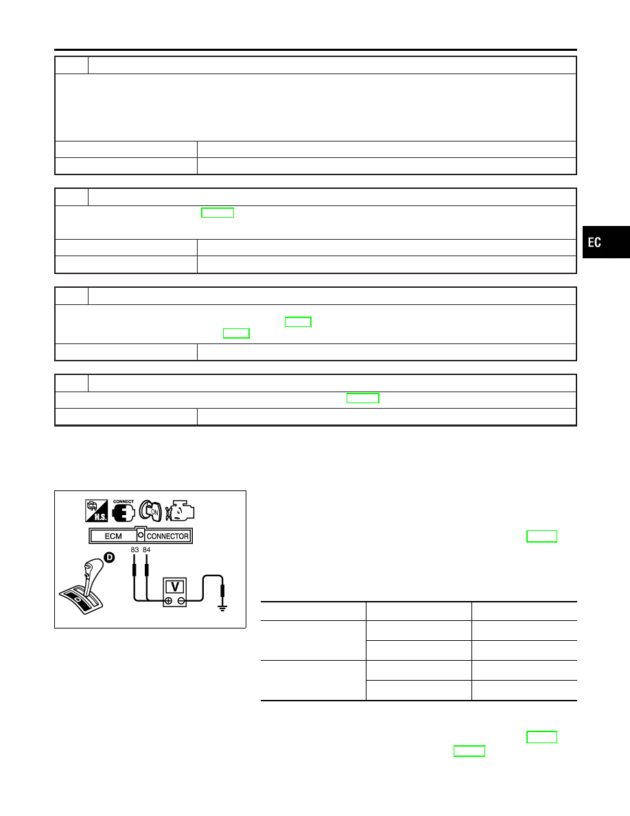
THROTTLE POSITION SENSOR
1.
Reconnect all harness connectors disconnected.
2.
Perform “Throttle Valve Closed Position Learning”, EC-70.
3.
Turn ignition switch ON.
4.
Set selector lever to D position.
5.
Check voltage between ECM terminals 83 (TP sensor 1), 84
(TP sensor 2) and ground under the following conditions.
Terminal
Accelerator pedal
Voltage
83
(Throttle position sensor
1)
Fully released
More than 0.36V
Fully depressed
Less than 4.75V
84
(Throttle position sensor
2)
Fully released
Less than 4.75V
Fully depressed
More than 0.36V
6.
If NG, replace electric throttle control actuator and go to the
next step.
7.
Perform “Throttle Valve Closed Position Learning”, EC-70.
8.
Perform “Idle Air Volume Learning”, EC-70.
GI
MA
EM
LC
FE
AT
AX
SU
BR
ST
RS
BT
HA
SC
EL
IDX
DTC P0122, P0123 TP SENSOR
Diagnostic Procedure (Cont’d)
EC-217