Infiniti I35 (A33). Manual - part 216
3
DETECT MALFUNCTIONING PART
Check harness for open or short between ECM and intake air temperature sensor.
©
Repair harness or connectors.
4
CHECK INTAKE AIR TEMPERATURE SENSOR GROUND CIRCUIT FOR OPEN AND SHORT
1. Turn ignition switch OFF.
2. Check harness continuity between sensor terminal 3 and ECM terminal 80.
Refer to Wiring Diagram.
Continuity should exist.
3. Also check harness for short to power.
OK or NG
OK
©
GO TO 6.
NG
©
GO TO 5.
5
DETECT MALFUNCTIONING PART
Check harness for open between ECM and intake air temperature sensor.
©
Repair open circuit or short to power in harness or connectors.
6
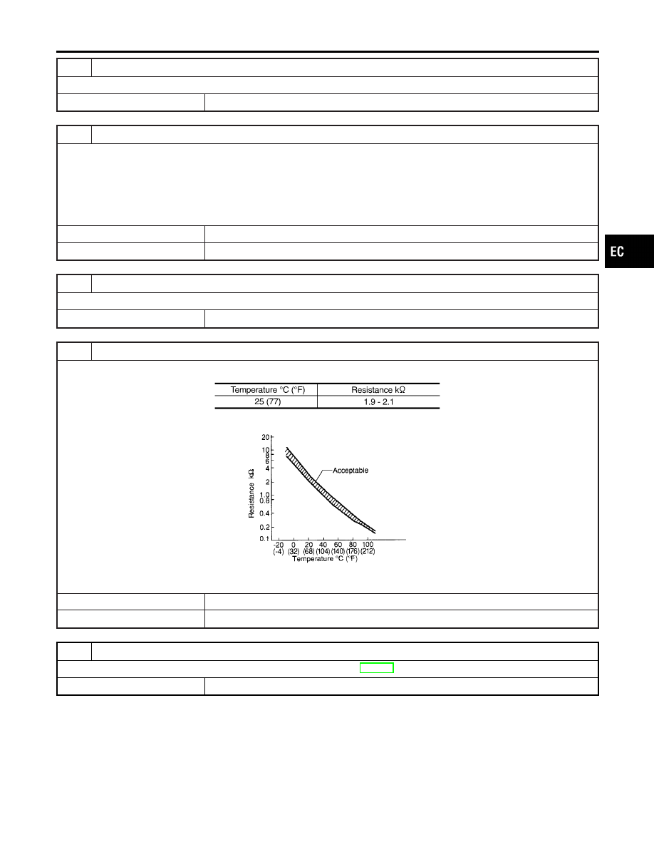
CHECK INTAKE AIR TEMPERATURE SENSOR
Check resistance between intake air temperature sensor terminals 3 and 5 as shown in the figure.
MTBL1143
SEF012P
OK or NG
OK
©
GO TO 7.
NG
©
Replace intake air temperature sensor.
7
CHECK INTERMITTENT INCIDENT
Refer to “TROUBLE DIAGNOSIS FOR INTERMITTENT INCIDENT”, EC-152.
©
INSPECTION END
GI
MA
EM
LC
FE
AT
AX
SU
BR
ST
RS
BT
HA
SC
EL
IDX
DTC P0112, P0113 IAT SENSOR
Diagnostic Procedure (Cont’d)
EC-205