Infiniti I35 (A33). Manual - part 211


  Index      Infiniti     Infiniti I35 (A33) - service repair manual 2004 year


Search            


Content   ..  209  210  211  212   ..


Infiniti I35 (A33). Manual - part 211


Diagnostic Procedure

NHEC0839

1

CHECK GROUND CONNECTIONS

1. Turn ignition switch OFF.
2. Loosen and retighten two engine ground screws.

Refer to “Ground Inspection”, EC-160.

SEC047D

OK or NG

OK

©

GO TO 2.

NG

©

Repair or replace ground connections.
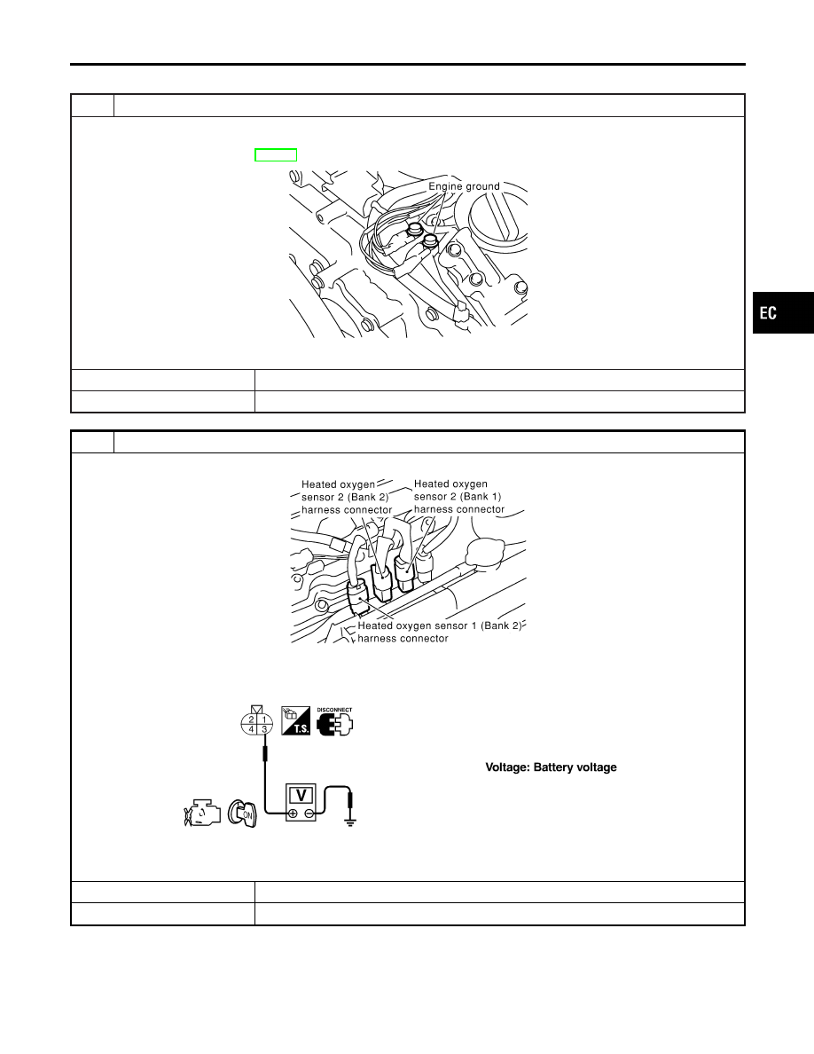
2

CHECK HO2S2 POWER SUPPLY CIRCUIT

1. Disconnect corresponding heated oxygen sensor 2 harness connector.

SEC134D

2. Turn ignition switch ON.
3. Check voltage between HO2S2 terminal 3 and ground.

SEF314X

OK or NG

OK

©

GO TO 4.

NG

©

GO TO 3.

GI

MA

EM

LC

FE

AT

AX

SU

BR

ST

RS

BT

HA

SC

EL

IDX

DTC P0037, P0038, P0057, P0058 HO2S2 HEATER

Diagnostic Procedure

EC-185

3

DETECT MALFUNCTIONING PART

Check the following.

I

Harness connectors M229, F66

I

Fuse block (J/B) connector M19

I

15A fuse

I

Harness for open or short between heated oxygen sensor 2 and fuse

©

Repair harness or connectors.

4

CHECK HO2S2 OUTPUT SIGNAL CIRCUIT FOR OPEN AND SHORT

1. Turn ignition switch OFF.
2. Disconnect ECM harness connector.
3. Check harness continuity between ECM terminal and HO2S2 terminal as follows.

Refer to Wiring Diagram.

MTBL1141

Continuity should exist.

4. Also check harness for short to ground and short to power.

OK or NG

OK

©

GO TO 5.

NG

©

Repair open circuit or short to ground or short to power in harness or connectors.

5

CHECK HEATED OXYGEN SENSOR 2 HEATER

Check the resistance between HO2S2 terminals as follows.

SEF315XG

CAUTION:

I

Discard any heated oxygen sensor which has been dropped from a height of more than 0.5 m (19.7 in) onto a
hard surface such as a concrete floor; use a new one.

I

Before installing new oxygen sensor, clean exhaust system threads using Oxygen Sensor Thread Cleaner tool
J-43897-18 or J-43897-12 and approved anti-seize lubricant.

OK or NG

OK

©

GO TO 6.

NG

©

Replace malfunctioning heated oxygen sensor 2.

6

CHECK INTERMITTENT INCIDENT

Refer to “TROUBLE DIAGNOSIS FOR INTERMITTENT INCIDENT”, EC-152.

©

INSPECTION END

DTC P0037, P0038, P0057, P0058 HO2S2 HEATER

Diagnostic Procedure (Cont’d)

EC-186

SEC266C

Component Description

NHEC0840

The mass air flow sensor is placed in the stream of intake air. It
measures the intake flow rate by measuring a part of the entire
intake flow. It consists of a hot film that is supplied with electric
current from the ECM. The temperature of the hot film is controlled
by the ECM a certain amount. The heat generated by the hot film
is reduced as the intake air flows around it. The more air, the
greater the heat loss.
Therefore, the ECM must supply more electric current to maintain
the temperature of the hot film as air flow increases. The ECM
detects the air flow by means of this current change.

CONSULT-II Reference Value in Data Monitor
Mode

NHEC0841

Specification data are reference values.

MONITOR ITEM

CONDITION

SPECIFICATION

MAS A/F SE-B1

I

Engine: After warming up

I

Air conditioner switch: OFF

I

Shift lever: N

I

No-load

Idle

1.1 - 1.5V

2,500 rpm

1.7 - 2.4V

CAL/LD VALUE

ditto

Idle

10 - 35%

2,500 rpm

10 - 35%

MASS AIRFLOW

ditto

Idle

2.0 - 6.0 g·m/s

2,500 rpm

7.0 - 20.0 g·m/s

On Board Diagnosis Logic

NHEC1428

This self-diagnosis has the one trip detection logic.
NOTE:
If DTC P0101 is displayed with DTC P1229, first perform the trouble diagnosis for DTC P1229. Refer to
EC-539.

DTC No.

Trouble diagnosis

name

DTC Detecting Condition

Possible Cause

P0101
0101

Mass air flow sensor
circuit range/
performance problem

A)

A high voltage from the sensor is sent to
ECM under light load driving condition.

I

Harness or connectors
(The sensor circuit is open or
shorted.)

I

Mass air flow sensor

B)

A low voltage from the sensor is sent to
ECM under heavy load driving condition.

I

Harness or connectors
(The sensor circuit is open or
shorted.)

I

Intake air leaks

I

Mass air flow sensor

DTC Confirmation Procedure

NHEC0844

Perform PROCEDURE MALFUNCTION A first. If the DTC can-
not be confirmed, perform PROCEDURE FOR MALFUNCTION
B.
NOTE:
If DTC Confirmation Procedure has been previously conducted,
always turn ignition switch OFF and wait at least 10 seconds before
conducting the next test.

GI

MA

EM

LC

FE

AT

AX

SU

BR

ST

RS

BT

HA

SC

EL

IDX

DTC P0101 MAF SENSOR

Component Description

EC-187

SEF174Y

PROCEDURE FOR MALFUNCTION A

NHEC0844S01

NOTE:
If engine will not start or stops soon, wait at least 10 seconds with
engine stopped (Ignition switch ON) instead of running engine at
idle speed.

With CONSULT-II

NHEC0844S0101

1)

Turn ignition switch ON.

2)

Select “DATA MONITOR” mode with CONSULT-II.

3)

Start engine and warm it up to normal operating temperature.

4)

Run engine for at least 10 seconds at idle speed.

5)

If DTC is detected, go to “Diagnostic Procedure”, EC-191.

With GST

NHEC0844S0102

Follow the procedure “With CONSULT-II” above.

SEF243Y

PBIB0199E

PROCEDURE FOR MALFUNCTION B

NHEC0844S02

CAUTION:

Always drive vehicle at a safe speed.

With CONSULT-II

NHEC0844S0201

1)

Turn ignition switch ON.

2)

Start engine and warm it up to normal operating temperature.
If engine cannot be started, go to “Diagnostic Procedure”,
EC-191.

3)

Select “DATA MONITOR” mode with CONSULT-II.

4)

Check the voltage of MAS A/F SE B1 with “DATA MONITOR”.

5)

Increases engine speed to about 4,000 rpm.

6)

Monitor the linear voltage rise in response to engine speed
increases.
If NG, go to “Diagnostic Procedure”, EC-191.
If OK, go to following step.

7)

Maintain the following conditions for at least 10 consecutive
seconds.

ENG SPEED

More than 2,000 rpm

THRTL SEN 1
THRTL SEN 2

More than 3V

Selector lever

Suitable position

Driving location

Driving vehicle uphill (Increased engine load)
will help maintain the driving conditions
required for this test.

8)

If DTC is detected, go to “Diagnostic Procedure”, EC-191.

DTC P0101 MAF SENSOR

DTC Confirmation Procedure (Cont’d)

EC-188


Content   ..  209  210  211  212   ..