Infiniti I35 (A33). Manual - part 207
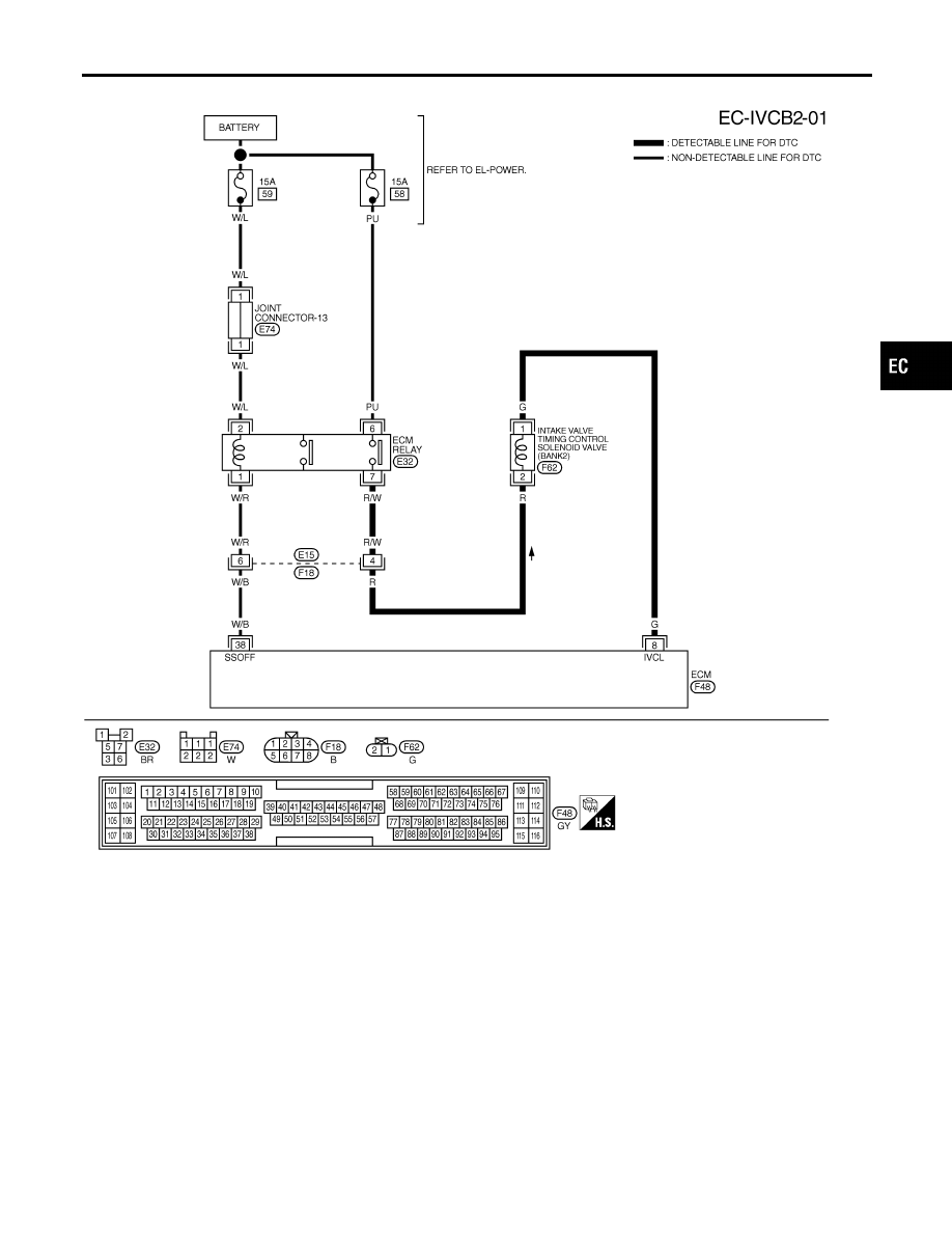
BANK 2
MEC348E
GI
MA
EM
LC
FE
AT
AX
SU
BR
ST
RS
BT
HA
SC
EL
IDX
DTC P0011, P0021 IVT CONTROL
Wiring Diagram (Cont’d)
EC-169
|
|
|
BANK 2 MEC348E GI MA EM LC FE AT AX SU BR ST RS BT HA SC EL IDX DTC P0011, P0021 IVT CONTROL Wiring Diagram (Cont’d) EC-169 |