Infiniti I35 (A33). Manual - part 206


  Index      Infiniti     Infiniti I35 (A33) - service repair manual 2004 year


Search            


Content   ..  204  205  206  207   ..


Infiniti I35 (A33). Manual - part 206


Description

NHEC0821

SYSTEM DESCRIPTION

NHEC0821S01

Sensor

Input signal to ECM function

ECM

Actuator

Crankshaft position sensor (POS)
Camshaft position sensor (PHASE)

Engine speed

Intake valve
timing con-
trol

Intake valve timing control sole-
noid valve

Engine coolant temperature sensor

Engine coolant temperature

Vehicle speed sensor

Vehicle speed

SEC419D

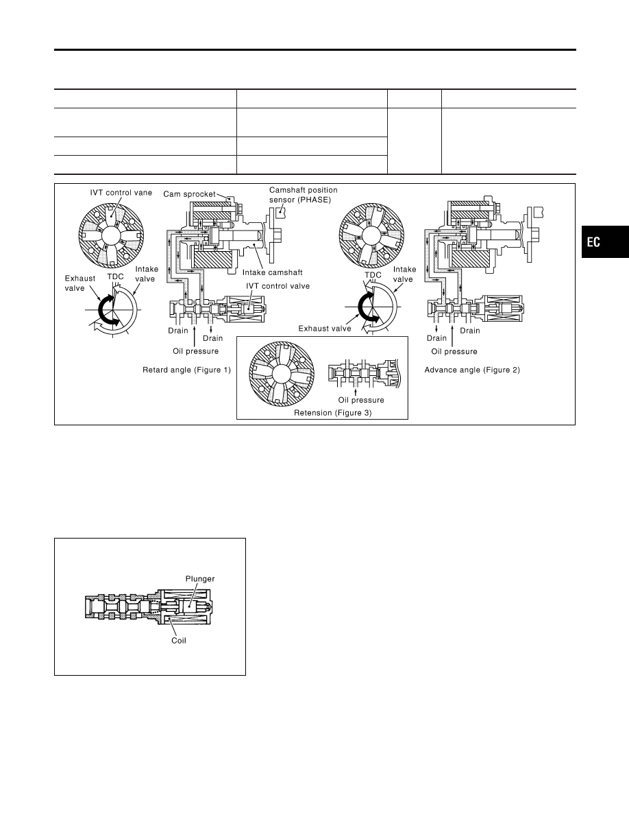
This mechanism hydraulically controls cam phases continuously with the fixed operating angle of the intake
valve.
The ECM receives signals such as crankshaft position, camshaft position, engine speed, and engine coolant
temperature. Then, the ECM sends ON/OFF pulse duty signals to the camshaft timing control valve depend-
ing on driving status. This makes it possible to control the shut/open timing of the intake valve to increase
engine torque in low/mid speed range and output in high-speed range.

COMPONENT DESCRIPTION

NHEC0821S02

PBIB1842E

Intake valve timing control solenoid valve is activated by ON/OFF pulse duty (ratio) signals from the ECM.
The intake valve timing control solenoid valve changes the oil amount and direction of flow through intake valve
timing control unit or stops oil flow.
The longer pulse width advantages valve angle.
The shorter pulse width retards valve angle.
When ON and OFF pulse widths become equal, the solenoid valve stops oil pressure flow to fix the intake
valve angle at the control position.

GI

MA

EM

LC

FE

AT

AX

SU

BR

ST

RS

BT

HA

SC

EL

IDX

DTC P0011, P0021 IVT CONTROL

Description

EC-165

CONSULT-II Reference Value in Data Monitor
Mode

NHEC0822

Specification data are reference values.

MONITOR ITEM

CONDITION

SPECIFICATION

INT/V TIM (B1)
INT/V TIM (B2)

I

Engine: After warming up

I

Shift lever N

I

Quickly depressed accelerator
pedal

I

No-load

Idle

−5 - 5° CA

2,000 rpm

Approximately 0 - 30° CA

INT/V SOL (B1)
INT/V SOL (B2)

I

Engine: After warming up

I

Shift lever N

I

Quickly depressed accelerator
pedal

I

No-load

Idle

0 - 2%

2,000 rpm

Approximately 25 - 50%

On Board Diagnosis Logic

NHEC0824

DTC No.

Trouble diagnosis

name

DTC Detecting Condition

Possible Cause

P0011
0011
(Bank 1)
P0021
0021
(Bank 2)

Intake valve timing
control performance

There is a gap between angle of target and
phase-control angle degree.

I

Harness or connectors
(Intake valve timing control solenoid
valve circuit is open or shorted.)

I

Intake valve timing control solenoid
valve

I

Crankshaft position sensor (POS)

I

Camshaft position sensor (PHASE)

I

Accumulation of debris to the signal
pick-up portion of the camshaft

FAIL-SAFE MODE

NHEC0824S01

When the malfunction is detected, the ECM enters fail-safe mode.

Detected items

Engine operating condition in fail-safe mode

Intake valve timing control

The signal is not energized to the solenoid valve and the valve control does not function.

DTC Confirmation Procedure

NHEC0825

CAUTION:

Always drive at a safe speed.
NOTE:
If

DTC

Confirmation

Procedure

has

been

previously

conducted, always turn ignition switch OFF and wait at least
10 seconds before conducting the next test.
TESTING CONDITION:
Before performing the following procedure, confirm that bat-
tery voltage is between 10V and 16V at idle.

DTC P0011, P0021 IVT CONTROL

CONSULT-II Reference Value in Data Monitor Mode

EC-166

SEF353Z

WITH CONSULT-II

NHEC0825S03

1)

Turn ignition switch ON.

2)

Select “DATA MONITOR” mode with CONSULT-II.

3)

Maintain the following conditions for at least 20 conecutive
seconds.

ENG SPEED

1,700 - 3,175 rpm (A constant rotation
is maintained.)

COOLANT TEMPS

70 - 105°C (158 - 221°F)

Selector lever

1st position

Driving location

Driving vehicle uphill
(Increased engine load will help main-
tain the driving conditions required for
this test.)

4)

If 1st trip DTC is detected, go to “Diagnostic Procedure”,
EC-171.

WITH GST

NHEC0825S04

Follow the procedure “WITH CONSULT-II” above.

GI

MA

EM

LC

FE

AT

AX

SU

BR

ST

RS

BT

HA

SC

EL

IDX

DTC P0011, P0021 IVT CONTROL

DTC Confirmation Procedure (Cont’d)

EC-167

Wiring Diagram

=NHEC1409

BANK 1

MEC575D

DTC P0011, P0021 IVT CONTROL

Wiring Diagram

EC-168


Content   ..  204  205  206  207   ..