Infiniti I35 (A33). Manual - part 192
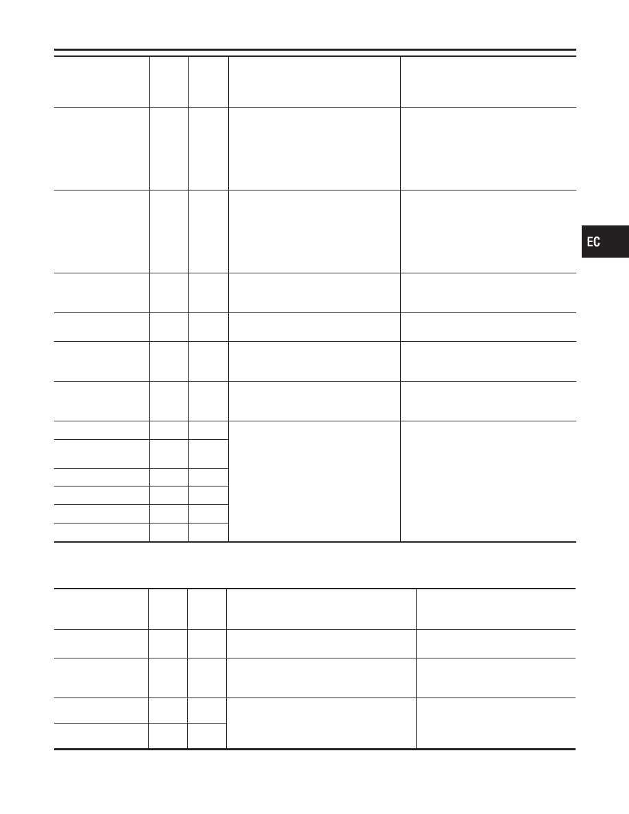
Monitored item [Unit]
ECM
INPUT
SIG-
NALS
MAIN
SIG-
NALS
Description
Remarks
VHCL SPD CUT
[NON/CUT]
I
Indicates the vehicle cruise condition.
NON...Vehicle speed is maintained at
the ASCD set speed.
CUT...Vehicle speed decreased to
excessively low compared with the
ASCD set speed, and ASCD operation
is cut off.
LO SPEED CUT
[NON/CUT]
I
Indicates the vehicle cruise condition.
NON...Vehicle speed is maintained at
the ASCD set speed.
CUT...Vehicle speed decreased to
excessively low compared with the
ASCD set speed, and ASCD operation
is cut off.
AT OD MONITOR
[ON/OFF]
I
Indicates [ON/OFF] condition of A/T
O/D according to the input signal from
the TCM.
AT OD CANCEL]
[ON/OFF]
I
Indicates [ON/OFF] condition of A/T OD
cancel signal sent from the TCM.
CRUISE LAMP
[ON/OFF]
I
Indicates [ON/OFF] condition CRUISE
lamp determined by the ECM according
to the input signals.
SET LAMP
[ON/OFF]
I
Indicates [ON/OFF] condition of SET
lamp determined by the ECM according
to the input signals.
Voltage [V]
I
Voltage, frequency, duty cycle or pulse
width measured by the probe.
I
Pulse width, frequency or duty cycle
measured by the pulse probe. Only
″
#
″
is displayed if item is unable to be
measured.
I
Figures with
″
#
″
s are temporary ones.
They are the same figures as an actual
piece of data which was just previously
measured.
Frequency [msec],
[Hz] or [%]
DUTY-HI
DUTY-LOW
PLS WIDTH-HI
PLS WIDTH-low
NOTE:
Any monitored item that does not match the vehicle being diagnosed is deleted from the display automatically.
DATA MONITOR (SPEC) MODE
NHEC0034S11
Monitored item [Unit]
ECM
input
signals
Main
signals
Description
Remarks
MAS A/F SE-B1 [V]
q
q
I
The signal voltage of the mass air flow sen-
sor specification is displayed.
I
When the engine is running, specifi-
cation range is indicated.
B/FUEL SCHDL
[msec]
I
“Base fuel schedule” indicates the fuel injec-
tion pulse width programmed into ECM,
prior to any learned on board correction.
I
When the engine is running, specifi-
cation range is indicated.
A/F ALPHA-B1 [%]
q
I
Indicates the mean value of the air-fuel ratio
feedback correction factor per cycle.
I
When the engine is running, specifi-
cation range is indicated.
I
This data also includes the data for
the air-fuel ratio learning control.
A/F ALPHA-B2 [%]
q
NOTE:
Any monitored item that does not match the vehicle being diagnosed is deleted from the display automatically.
GI
MA
EM
LC
FE
AT
AX
SU
BR
ST
RS
BT
HA
SC
EL
IDX
ON BOARD DIAGNOSTIC SYSTEM DESCRIPTION
CONSULT-II (Cont’d)
EC-109