Infiniti I35 (A33). Manual - part 190


  Index      Infiniti     Infiniti I35 (A33) - service repair manual 2004 year


Search            


Content   ..  188  189  190  191   ..


Infiniti I35 (A33). Manual - part 190


Item

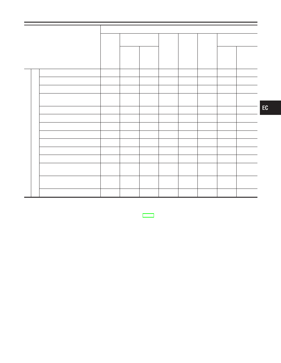
DIAGNOSTIC TEST MODE

WORK

SUP-

PORT

SELF-DIAGNOSTIC

RESULTS

DATA

MONI-

TOR

DATA

MONI-

TOR

(SPEC)

ACTIVE

TEST

DTC & SRT

CONFIRMATION

DTC*1

FREEZE

FRAME
DATA*2

SRT

STATUS

DTC

WORK

SUP-

PORT

ENGINE

CONTROL

COMPONENT

P

ARTS

OUTPUT

Injectors

X

X

X

Power transistor (Ignition timing)

X

X

X

Throttle control motor relay

X

X

X

EVAP canister purge volume
control solenoid valve

X

X

X

X

X

Air conditioner relay

X

X

Fuel pump relay

X

X

X

X

Heated oxygen sensor 1 heater

X

X

X

X

Heated oxygen sensor 2 heater

X

X

X

X

EVAP canister vent control valve

X

X

X

X

X

Vacuum cut valve bypass valve

X

X

X

X

X

X

VIAS control solenoid valve

X

X

X

X

Intake valve timing control sole-
noid valve

X

X

X

X

Electronic controlled engine
mount

X

X

X

Calculated load value

X

X

X

X: Applicable
*1: This item includes 1st trip DTCs.
*2: This mode includes 1st trip freeze frame data or freeze frame data. The items appear on CONSULT-II screen in freeze frame data
mode only if a 1st trip DTC or DTC is detected. For details, refer to EC-76.

GI

MA

EM

LC

FE

AT

AX

SU

BR

ST

RS

BT

HA

SC

EL

IDX

ON BOARD DIAGNOSTIC SYSTEM DESCRIPTION

CONSULT-II (Cont’d)

EC-101

FUNCTION

=NHEC0034S03

Diagnostic test mode

Function

WORK SUPPORT

This mode enables a technician to adjust some devices faster and more accurately by following the
indications on the CONSULT-II unit.

SELF-DIAG RESULTS

Self-diagnostic results such as 1st trip DTC, DTCs and 1st trip freeze frame data or freeze frame
data can be read and erased quickly.*1

DATA MONITOR

Input/Output data in the ECM can be read.

DATA MONITOR (SPEC)

Input/Output specification of the basic fuel schedule, AFM, A/F feedback control value and the
other data monitor items can be read.

CAN DIAGNOSTIC SUP-
PORT MONITOR

The results of transmit/receive diagnosis of CAN communication can be read.

ACTIVE TEST

Diagnostic Test Mode in which CONSULT-II drives some actuators apart from the ECMs and also
shifts some parameters in a specified range.

FUNCTION TEST

Conducted by CONSULT-II instead of a technician to determine whether each system is “OK” or
“NG”.

DTC & SRT CONFIRMA-
TION

The status of system monitoring tests and the self-diagnosis status/result can be confirmed.

ECM PART NUMBER

ECM part number can be read.

*1 The following emission-related diagnostic information is cleared when the ECM memory is erased.
1)

Diagnostic trouble codes

2)

1st trip diagnostic trouble codes

3)

Freeze frame data

4)

1st trip freeze frame data

5)

System readiness test (SRT) codes

6)

Test values

7)

Others

ON BOARD DIAGNOSTIC SYSTEM DESCRIPTION

CONSULT-II (Cont’d)

EC-102

WORK SUPPORT MODE

=NHEC0034S04

WORK ITEM

CONDITION

USAGE

FUEL PRESSURE RELEASE

I

FUEL PUMP WILL STOP BY TOUCHING “START”
DURING IDLING.
CRANK A FEW TIMES AFTER ENGINE STALLS.

When releasing fuel pressure
from fuel line

IDLE AIR VOL LEARN

I

THE IDLE AIR VOLUME THAT KEEPS THE ENGINE
WITHIN THE SPECIFIED RANGE IS MEMORIZED IN
ECM.

When learning the idle air volume

SELF-LEARNING CONT

I

THE COEFFICIENT OF SELF-LEARNING CONTROL
MIXTURE RATIO RETURNS TO THE ORIGINAL
COEFFICIENT.

When clearing the coefficient of
self-learning control value

EVAP SYSTEM CLOSE

OPEN THE VACUUM CUT VALVE BYPASS VALVE AND
CLOSE THE EVAP CANISTER VENT CONTROL VALVE
IN ORDER TO MAKE EVAP SYSTEM CLOSE UNDER
THE FOLLOWING CONDITIONS.

I

IGN SW ON

I

ENGINE NOT RUNNING

I

AMBIENT TEMPERATURE IS ABOVE 0°C (32°F).

I

NO VACUUM AND NO HIGH PRESSURE IN EVAP
SYSTEM

I

TANK FUEL TEMP. IS MORE THAN 0°C (32°F).

I

WITHIN 10 MINUTES AFTER STARTING “EVAP SYS-
TEM CLOSE”

I

WHEN TRYING TO EXECUTE “EVAP SYSTEM
CLOSE” UNDER THE CONDITION EXCEPT ABOVE,
CONSULT-II WILL DISCONTINUE IT AND DISPLAY
APPROPRIATE INSTRUCTION.
NOTE:
WHEN STARTING ENGINE, CONSULT-II MAY DIS-
PLAY “BATTERY VOLTAGE IS LOW. CHARGE
BATTERY”, EVEN IN USING CHARGED BATTERY.

When detecting EVAP vapor leak
point of EVAP system

TARGET IGN TIM ADJ*

I

IDLE CONDITION

I

When adjusting target ignition
timing
After adjustment, confirm target
ignition timing with a timing
light.

I

If once the “TARGET IDLE
RPM ADJ” has been done, the
Idle Air Volume Learning proce-
dure will not be completed.

TARGET IDLE RPM ADJ*

I

IDLE CONDITION

When setting target idle speed

*: This function is not necessary in the usual service procedure.

SELF-DIAGNOSTIC MODE

NHEC0034S05

DTC and 1st Trip DTC

NHEC0034S0501

Regarding items of DTC and 1st trip DTC, refer to “TROUBLE
DIAGNOSIS — INDEX” (See EC-9.)

Freeze Frame Data and 1st Trip Freeze Frame Data

NHEC0034S0502

Freeze frame data

item*1

Description

DIAG TROUBLE
CODE
[PXXXX]

I

The engine control component part/control system has a trouble code, it is displayed as “PXXXX”.
(Refer to “TROUBLE DIAGNOSIS — INDEX”, EC-9.)

GI

MA

EM

LC

FE

AT

AX

SU

BR

ST

RS

BT

HA

SC

EL

IDX

ON BOARD DIAGNOSTIC SYSTEM DESCRIPTION

CONSULT-II (Cont’d)

EC-103

Freeze frame data

item*1

Description

FUEL SYS-B1

I

“Fuel injection system status” at the moment a malfunction is detected is displayed.

I

One mode in the following is displayed.
“Mode2”: Open loop due to detected system malfunction
“Mode3”: Open loop due to driving conditions (power enrichment, deceleration enleanment)
“Mode4”: Closed loop - using oxygen sensor(s) as feedback for fuel control
“Mode5”: Open loop - has not yet satisfied condition to go to closed loop

FUEL SYS-B2

CAL/LD VALUE [%]

I

The calculated load value at the moment a malfunction is detected is displayed.

COOLANT TEMP [°C]
or [°F]

I

The engine coolant temperature at the moment a malfunction is detected is displayed.

S-FUEL TRM-B1 [%]

I

“Short-term fuel trim” at the moment a malfunction is detected is displayed.

I

The short-term fuel trim indicates dynamic or instantaneous feedback compensation to the base fuel
schedule.

S-FUEL TRM-B2 [%]

L-FUEL TRM-B1 [%]

I

“Long-term fuel trim” at the moment a malfunction is detected is displayed.

I

The long-term fuel trim indicates much more gradual feedback compensation to the base fuel schedule
than short-term fuel trim.

L-FUEL TRM-B2 [%]

ENGINE SPEED
[rpm]

I

The engine speed at the moment a malfunction is detected is displayed.

VEHICL SPEED
[km/h] or [mph]

I

The vehicle speed at the moment a malfunction is detected is displayed.

B/FUEL SCHDL
[msec]

I

The base fuel schedule at the moment a malfunction is detected is displayed.

INT/A TEMP SE [°C]
or [°F]

I

The intake air temperature at the moment a malfunction is detected is displayed.

*1: The items are the same as those of 1st trip freeze frame data.

ON BOARD DIAGNOSTIC SYSTEM DESCRIPTION

CONSULT-II (Cont’d)

EC-104


Content   ..  188  189  190  191   ..