Infiniti I35 (A33). Manual - part 181
16
CHECK TIMING CHAIN INSTALLATION
Check timing chain installation. Refer to EM-29, “TIMING CHAIN”.
OK or NG
OK
©
GO TO 17.
NG
©
1. Repair the timing chain installation.
2. GO TO 4.
17
DETECT MALFUNCTIONING PART
Check the following.
I
Check camshaft position sensor (PHASE) and circuit. Refer to “DTC P0340, P0345 CMP SENSOR (PHASE)”, EC-323.
I
Check crankshaft position sensor (POS) and circuit. Refer to “DTC P0335 CKP SENSOR (POS)”, EC-316.
OK or NG
OK
©
GO TO 18.
NG
©
1. Repair or replace.
2. GO TO 4.
18
CHECK ECM FUNCTION
1. Substitute another known-good ECM to check ECM function. (ECM may be the cause of an incident, but this is a rare
case.)
2. Perform initialization of IVIS (NATS) system and registration of all IVIS (NATS) ignition key IDs. Refer to “IVIS (INFINITI
VEHICLE IMMOBILIZER SYSTEM — NATS)”, EC-90.
©
GO TO 4.
19
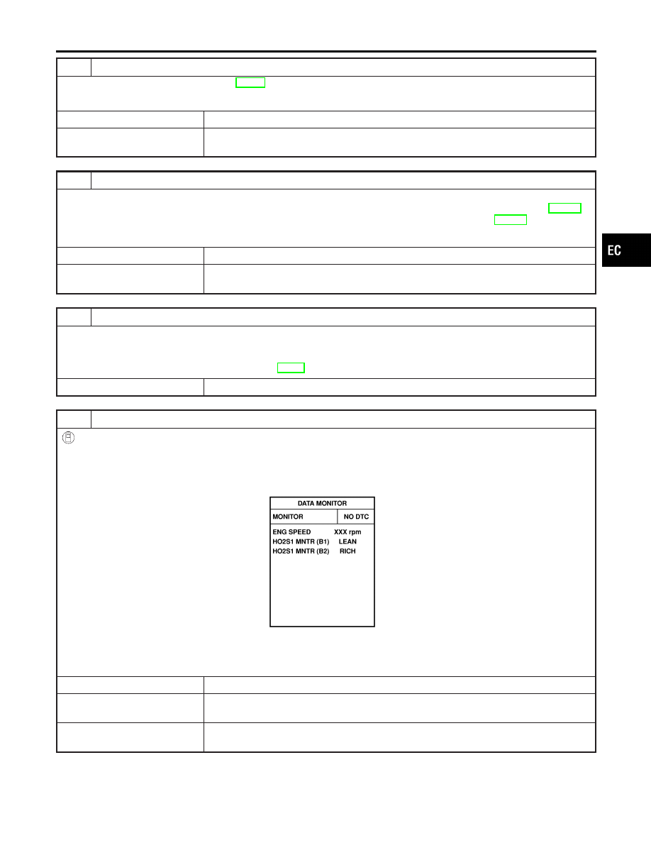
CHECK HEATED OXYGEN SENSOR 1 (BANK 1) SIGNAL
With CONSULT-II
1. Run engine at about 2,000 rpm for about 2 minutes under no-load.
2. See “HO2S1 MNTR (B1)” in “DATA MONITOR” mode.
3. Running engine at 2,000 rpm under no-load (The engine is warmed up to normal operating temperature.), check that
the monitor fluctuates between LEAN and RICH more than 5 times during 10 seconds.
PBIB0120E
1 time: RICH
→
LEAN
→
RICH
2 times: RICH
→
LEAN
→
RICH
→
LEAN
→
RICH
OK or NG
OK
©
GO TO 21.
NG (Monitor does not
fluctuate.)
©
GO TO 23.
NG (Monitor fluctuates
less than 5 times.)
©
GO TO 30.
GI
MA
EM
LC
FE
AT
AX
SU
BR
ST
RS
BT
HA
SC
EL
IDX
BASIC SERVICE PROCEDURE
Idle Speed/Ignition Timing/Idle Mixture Ratio Adjustment (Cont’d)
EC-65