Infiniti I35 (A33). Manual - part 172
MEC631E
GI
MA
EM
LC
FE
AT
AX
SU
BR
ST
RS
BT
HA
SC
EL
IDX
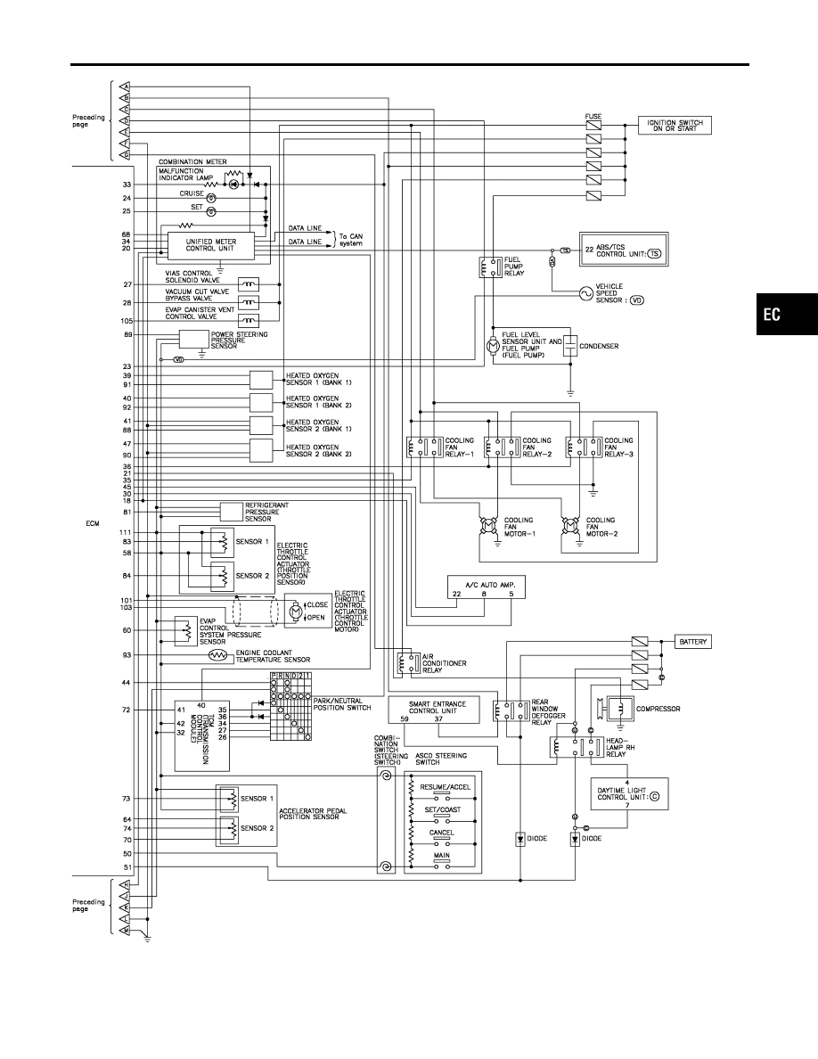
ENGINE AND EMISSION CONTROL OVERALL SYSTEM
Circuit Diagram (Cont’d)
EC-29
|
|
|
MEC631E GI MA EM LC FE AT AX SU BR ST RS BT HA SC EL IDX ENGINE AND EMISSION CONTROL OVERALL SYSTEM Circuit Diagram (Cont’d) EC-29 |