Infiniti I35 (A33). Manual - part 151
SBT863
GI
MA
EM
LC
EC
FE
AT
AX
SU
BR
ST
RS
HA
SC
EL
IDX
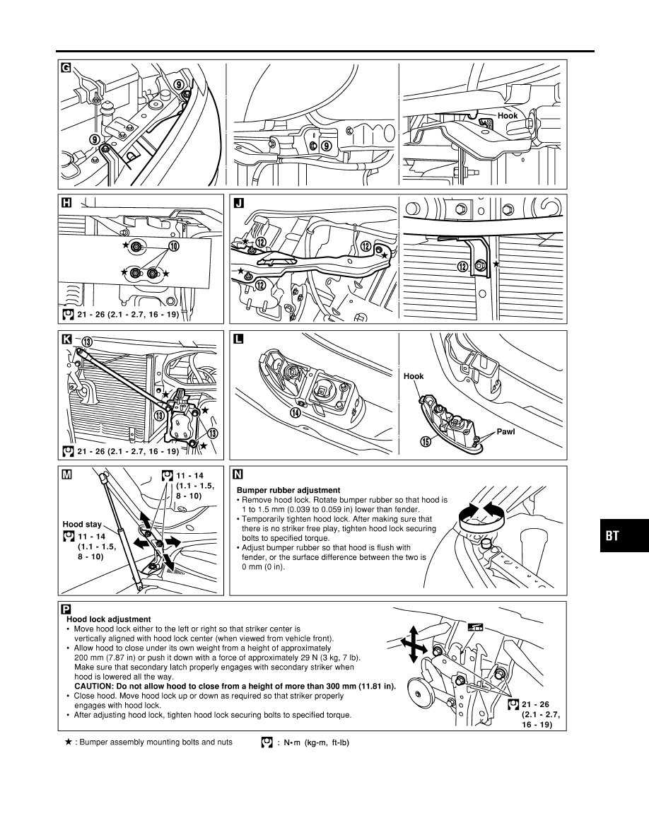
BODY FRONT END
Removal and Installation (Cont’d)
BT-15
|
|
|
SBT863 GI MA EM LC EC FE AT AX SU BR ST RS HA SC EL IDX BODY FRONT END Removal and Installation (Cont’d) BT-15 |