Infiniti I35 (A33). Manual - part 143
4
CHECK CONNECTOR
1. Turn ignition switch OFF, disconnect the ABS actuator and electric unit (control unit) connector, and check the terminal
for deformation, disconnection, looseness, etc. If there is a malfunction, repair or replace the terminal.
2. Reconnect connector to perform self-diagnosis.
Is only “CAN COMM CIRCUIT” indicated in the self-diagnosis results?
Yes
©
Print out the self-diagnostic results. Refer to EL-463.
No
©
Connector terminal connection is loose, damaged, open or shorted.
SBR222F
Component Check
NHBR0285
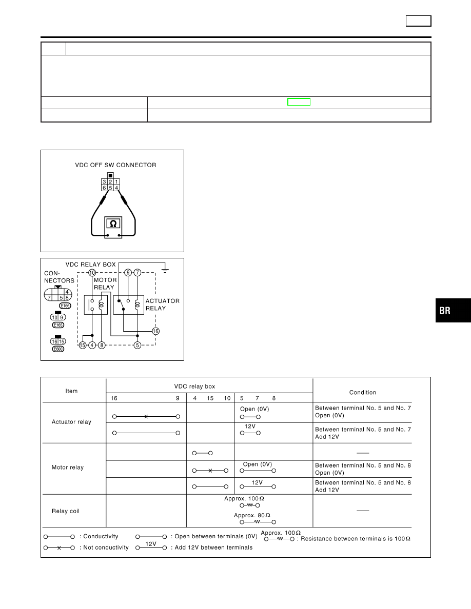
VDC OFF SWITCH
NHBR0285S01
I
Disconnect the VDC OFF switch connector M220. Check for
continuity between the terminal No. 4 and No. 5.
4 - 5
Pressing the switch will make a continuity, and
releasing it will stop the continuity.
SBR223F
VDC RELAY BOX
NHBR0285S02
Disconnect the VDC relay box connectors E165, E166 and E600.
Check for continuity, resistance value, and insulation between any
pair of terminals in the VDC relay box.
Continuity and Resistance
NHBR0285S0201
SBR224F
GI
MA
EM
LC
EC
FE
AT
AX
SU
ST
RS
BT
HA
SC
EL
IDX
TROUBLE DIAGNOSES FOR SELF-DIAGNOSTIC ITEMS
VDC
Inspection 15 CAN Communication Circuit, VDC/TCS/ABS Control Unit and Steering Angle Sensor (Cont’d)
BR-157