Infiniti I35 (A33). Manual - part 142


  Index      Infiniti     Infiniti I35 (A33) - service repair manual 2004 year


Search            


Content   ..  140  141  142  143   ..


Infiniti I35 (A33). Manual - part 142


5

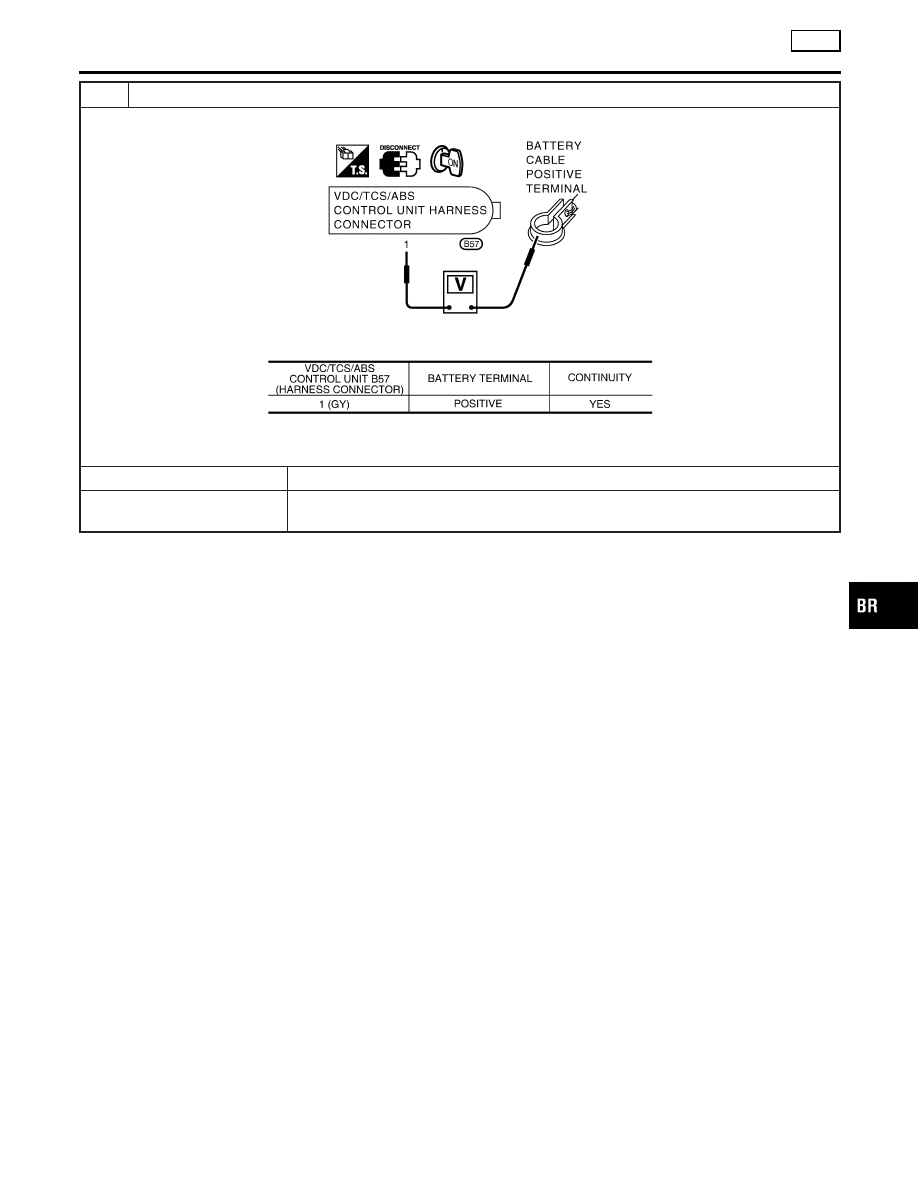
VDC/TCS/ABS CONTROL UNIT POWER SUPPLY CIRCUIT INSPECTION 2

1. Check the fuse 10A.

SBR216F

2. Check for continuity between the battery positive terminal and the VDC/TCS/ABS control unit connector B57.

MTBL1397

Is inspection result OK?

Yes

©

Check the battery for a loose terminal and low voltage or the alternator for abnormality.

No

©

I

Replace the fuse 10A.

I

Harness disconnection

GI

MA

EM

LC

EC

FE

AT

AX

SU

ST

RS

BT

HA

SC

EL

IDX

TROUBLE DIAGNOSES FOR SELF-DIAGNOSTIC ITEMS

VDC

Inspection 11 VDC/TCS/ABS Control Unit Power Supply Circuit (Cont’d)

BR-153

Inspection 12 When “EMERGENCY BRAKE” Is
Indicated in The Self-diagnosis Results

=NHBR0281

Inspection procedure

1

SELF-DIAGNOSIS RESULT CHECK

Check the self-diagnosis results.

MTBL1292

When any items other than “EMERGENCY BRAKE” is displayed in the self-diagnosis results, follow the instructions below.

CAUTION:

“EMERGENCY BRAKE” is indicated when the control unit itself is detected internal error. If this display item was
indicated, replace the control unit.

Is “EMERGENCY BRAKE” is indicated in the self-diagnosis results?

©

Replace the VDC/TCS/ABS control unit, and perform the self-diagnosis again.

Inspection 13 When “ST ANG SEN SIGNAL” is
Indicated in The Self-diagnosis Results

NHBR0282

Inspection procedure

1

SELF-DIAGNOSIS RESULT CHECK 1

Check the self-diagnosis results.

MTBL1293

When any items other than “ST ANGLE SEN SIGNAL” is displayed in the self-diagnosis results:

Yes

©

Check and repair the applicable items. Perform the self-diagnosis again.

No

©

Perform the steering angle sensor neutral position adjustment. GO TO 2.

2

SELF-DIAGNOSIS RESULT CHECK 2

Turn the ignition switch OFF, and ON to erase the self-diagnosis results. And perform the VDC/TCS/ABS control unit self-
diagnosis again.

Is the same self-diagnosis item indicated again?

Yes

©

After replacing the spiral cable (with the steering angle sensor), perform the neutral posi-
tion adjustment. Then conduct the self-diagnosis again.

No

©

INSPECTION END

TROUBLE DIAGNOSES FOR SELF-DIAGNOSTIC ITEMS

VDC

Inspection 12 When “EMERGENCY BRAKE” Is Indicated in The Self-diagnosis Results

BR-154

Inspection 14 Brake Fluid Level of Reservoir
Tank

NHBR0283

Inspection procedure

1

SELF-DIAGNOSIS RESULT CHECK 1

Check the self-diagnosis results.

MTBL1294

Does the brake warning light turn on?

Yes

©

Check the pad for wear. Check the brake fluid for leakage.

No

©

GO TO 2.

2

SELF-DIAGNOSIS RESULT CHECK 2

1. Disconnect connectors for the brake fluid level warning switch and the VDC/TCS/ABS control unit.
2. Securely connect connectors. Perform the VDC/TCS/ABS control unit self-diagnosis again.

Is the same self-diagnosis item indicated again?

Yes

©

Poor connection of connector. Repair or replace the poorly connected connector.

No

©

GO TO 3.

3

CIRCUIT CHECK BETWEEN BRAKE FLUID LEVEL WARNING SWITCH AND VDC/TCS/ABS CONTROL
UNIT

1. Disconnect connectors for the brake fluid level warning switch and the VDC/TCS/ABS control unit.

SBR218F

2. Check for continuity between the brake fluid level warning switch (harness connector E1) and the VDC/TCS/ABS con-

trol unit (harness connector B57).

MTBL1398

Is inspection result OK?

OK

©

Perform the VDC/TCS/ABS control unit self-diagnosis again.

NG

©

Repair or replace the disconnected harness.

GI

MA

EM

LC

EC

FE

AT

AX

SU

ST

RS

BT

HA

SC

EL

IDX

TROUBLE DIAGNOSES FOR SELF-DIAGNOSTIC ITEMS

VDC

Inspection 14 Brake Fluid Level of Reservoir Tank

BR-155

Inspection 15 CAN Communication Circuit,
VDC/TCS/ABS Control Unit and Steering Angle
Sensor

NHBR0284

Inspection procedure

1

SELF-DIAGNOSIS RESULT CHECK 1

Check the self-diagnosis results.

MTBL1296

Are any items other than above indicated in self-diagnosis results?

Yes

©

Repair or replace affected items.

No

©

GO TO 2.

2

CHECK HARNESS AND CONNECTORS BETWEEN VDC/TCS/ABS CONTROL UNIT AND STEERING
ANGLE SENSOR

1. Turn the ignition switch OFF, and disconnect the battery negative terminal.
2. Disconnect the VDC/TCS/ABS control B57 unit connector and the steering angle sensor connector M218.

SBR220F

3. Check the harness between the VDC/TCS/ABS control unit connector B57 and the steering angle sensor connector

M218 for open and short circuit.

MTBL1399

4. Check connectors for the control unit and the sensor.

Check the connector housing for disconnected, loose, bent, and collapsed terminals.

Is inspection result OK?

OK

©

GO TO 3.

NG

©

Repair disconnected harness or poorly connected connectors. GO TO 3.

3

SELF-DIAGNOSIS RESULT CHECK 2

1. Connect connectors to the control unit and the sensor.
2. Connect the battery negative terminal, and turn the ignition switch ON.
3. After erasing the self-diagnosis result, start the engine to perform the self-diagnosis again.

Is only “ST ANGLE SEN COM CIR” indicated in the self-diagnosis results?

Yes

©

Replace the spiral cable (with the steering angle sensor) and adjust the neutral position
of the steering angle sensor. Refer to ON-VEHICLE SERVICE, BR-93.

No

©

GO TO 4.

TROUBLE DIAGNOSES FOR SELF-DIAGNOSTIC ITEMS

VDC

Inspection 15 CAN Communication Circuit, VDC/TCS/ABS Control Unit and Steering Angle Sensor

BR-156


Content   ..  140  141  142  143   ..