Infiniti I35 (A33). Manual - part 125
2
CHECK FUSE
Check 10A fuse No. 30 for ABS actuator and electric unit (control unit). For fuse layout, refer to “POWER SUPPLY ROUT-
ING” in EL section.
Is fuse OK?
Yes
©
GO TO 3.
No
©
Replace fuse.
3
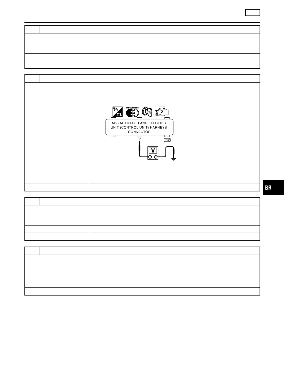
CHECK CONTROL UNIT POWER SUPPLY CIRCUIT
1. Install 10A fuse.
2. Disconnect connector from ABS actuator and electric unit (control unit) E162.
3. Check voltage between ABS actuator and electric unit (control unit) harness connector E162 terminal 26 (R/Y) and
ground after turning ignition switch “ON”.
SBR178F
Does battery voltage exist?
Yes
©
GO TO 5.
No
©
GO TO 4.
4
CHECK COMBINATION METER CIRCUIT
I
Check continuity between ABS actuator and electric unit (control unit) and combination meter.
I
Check continuity between combination meter and fuse.
Does continuity exist?
Yes
©
Replace combination meter.
No
©
Repair or replace harness connector.
5
CHECK CONNECTOR
1. Disconnect connector from ABS actuator and electric unit (control unit) E162. Check terminals for damage or loose
connection. Then reconnect connector.
2. Carry out self-diagnosis again.
Does warning lamp activate again?
Yes
©
Check items the self-diagnosis detected as faulty.
No
©
INSPECTION END
GI
MA
EM
LC
EC
FE
AT
AX
SU
ST
RS
BT
HA
SC
EL
IDX
TROUBLE DIAGNOSES FOR SYMPTOMS
TCS
9. TCS OFF Indicator Lamp Does Not Come On When Ignition Switch Is Turned On (Cont’d)
BR-85