Infiniti I35 (A33). Manual - part 95


  Index      Infiniti     Infiniti I35 (A33) - service repair manual 2004 year


Search            


Content   ..  93  94  95  96   ..


Infiniti I35 (A33). Manual - part 95


SAT235F

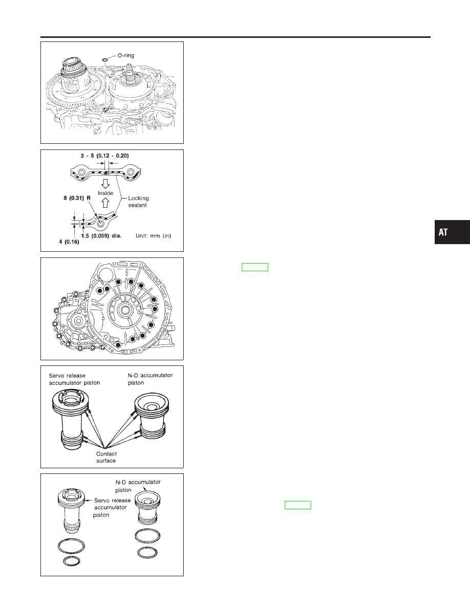
12. Install O-ring on differential oil port of transmission case.

SAT371H

13. Install converter housing on transmission case.

I

Apply Anaerobic Liquid Gasket or equivalent* to mating
surface of converter housing.
*: Refer to GI section.

SAT008F

I

Tighten converter housing bolts to the specified torque.
Refer to AT-288.

SAT406DA

14. Install accumulator piston.
a.

Check contact surface of accumulator piston for damage.

SAT236FA

b.

Install O-rings on accumulator piston.

I

Apply ATF to O-rings.

Accumulator piston O-rings:

Refer to SDS, AT-382.

GI

MA

EM

LC

EC

FE

AX

SU

BR

ST

RS

BT

HA

SC

EL

IDX

ASSEMBLY

Assembly (3) (Cont’d)

AT-377

SAT237FA

c.

Install accumulator pistons and return springs on transmission
case.

I

Apply ATF to inner surface of transmission case.

Return springs:

Refer to SDS, AT-383.

SAT006F

15. Install lip seals for band servo oil holes on transmission case.

I

Apply petroleum jelly to lip seals.

SAT862HA

16. Install L & R oil tube and oil sleeve. Tighten L & R oil tube bolts

to the specified torque. Refer to AT-288.

SAT005F

17. Install control valve assembly.
a.

Insert manual valve into control valve assembly.

I

Apply ATF to manual valve.

SAT094J

b.

Set manual shaft in Neutral position.

c.

Install control valve assembly on transmission case while
aligning manual valve with manual plate.

ASSEMBLY

Assembly (3) (Cont’d)

AT-378

SAT416D

d.

Pass solenoid harness through transmission case and install
terminal body on transmission case by pushing it.

e.

Install stopper ring to terminal body.

SAT004F

f.

Tighten bolts Iand

I

.

Bolt length, number and location:

Bolt

I

X

I

Bolt length “


mm (in)

40

(1.57)

33

(1.30)

43.5

(1.713)

Number of bolts

5

6

2

SAT003F

18. Install oil pan.
a.

Attach a magnet to oil pan.

b.

Install new oil pan gasket on transmission case.

c.

Install oil pan on transmission case.

I

Always replace oil pan bolts as they are self-sealing bolts.

I

Tighten four bolts in a criss-cross pattern to prevent dis-
location of gasket.

d.

Tighten oil pan bolts and drain plug to the specified torque.
Refer to AT-288.

SAT033J

19. Install park/neutral position (PNP) switch.
a.

Set manual shaft in P position.

b.

Temporarily install park/neutral position (PNP) switch on
manual shaft.

c.

Move selector lever to N position.

GI

MA

EM

LC

EC

FE

AX

SU

BR

ST

RS

BT

HA

SC

EL

IDX

ASSEMBLY

Assembly (3) (Cont’d)

AT-379

AAT469A

d.

Use a 4 mm (0.16 in) pin for this adjustment.

i.

Insert the pin straight into the manual shaft adjustment hole.

ii.

Rotate park/neutral position (PNP) switch until the pin can also
be inserted straight into hole in park/neutral position (PNP)
switch.

e.

Tighten park/neutral position (PNP) switch fixing bolts. Refer to
AT-288.

f.

Remove pin from adjustment hole after adjusting park/neutral
position (PNP) switch.

SAT768J

20. Install A/T fluid charging pipe and fluid cooler tube to transmis-

sion case. Tighten A/T fluid charging pipe and fluid cooler tube
bolts to the specified torque. Refer to AT-288.

SAT428DA

21. Install torque converter.
a.

Pour ATF into torque converter.

I

Approximately 1 liter (1-1/8 US qt, 7/8 Imp qt) of fluid is
required for a new torque converter.

I

When reusing old torque converter, add the same amount
of fluid as was drained.

SAT429D

b.

Install torque converter while aligning notches of torque con-
verter with notches of oil pump.

SAT430D

c.

Measure distance “A” to check that torque converter is in
proper position.

Distance A:

Refer to SDS, AT-390.

ASSEMBLY

Assembly (3) (Cont’d)

AT-380


Content   ..  93  94  95  96   ..