Infiniti I35 (A33). Manual - part 92
SAT337D
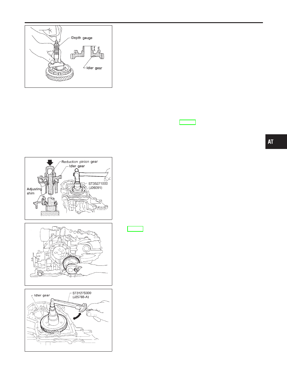
d.
Measure dimension “E” between the end of idler gear and the
idler gear bearing inner race mating surface of idler gear.
I
Measure dimension “E” in at least two places.
e.
Select proper thickness of reduction pinion gear bearing
adjusting shim.
Proper shim thickness = A − E − 0.05 mm (0.0020 in)*
(* ... Bearing preload)
Reduction pinion gear bearing adjusting shim:
Refer to SDS, AT-387.
SAT873DD
3.
Install reduction gear and reduction gear bearing adjusting
shim selected in step 2-e on transmission case.
4.
Press idler gear bearing inner race on idler gear.
5.
Press idler gear on reduction gear.
I
Press idler gear until idler gear fully contacts adjusting
shim.
SAT189F
6.
Tighten idler gear lock nut to the specified torque. Refer to
AT-348.
I
Lock idler gear with parking pawl when tightening lock
nut.
SAT190FA
7.
Measure turning torque of reduction pinion gear.
I
When measuring turning torque, turn reduction pinion
gear in both directions several times to seat bearing roll-
ers correctly.
Turning torque of reduction pinion gear:
0.05 - 0.39 N·m (0.5 - 4.0 kg-cm, 0.43 - 3.47 in-lb)
I
If turning torque is out of specification, decrease or
increase thickness of reduction pinion gear bearing
adjusting shim.
GI
MA
EM
LC
EC
FE
AX
SU
BR
ST
RS
BT
HA
SC
EL
IDX
ASSEMBLY
Adjustment (1) (Cont’d)
AT-365