Infiniti I35 (A33). Manual - part 90
AAT882
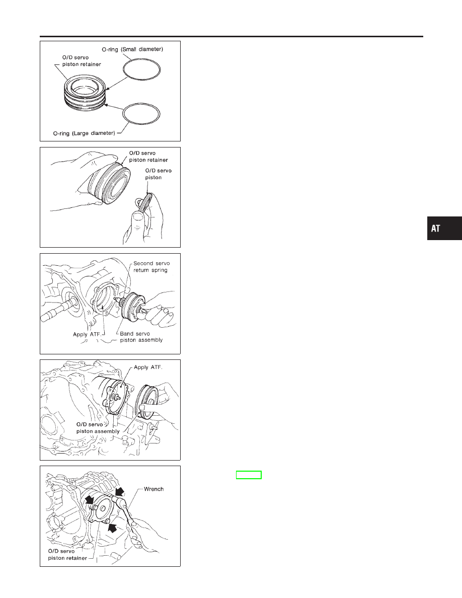
7.
Install O-rings to O/D servo piston retainer.
I
Apply ATF to O-rings.
I
Pay attention to position of each O-ring.
AAT886
8.
Install O/D servo piston to O/D servo piston retainer.
SAT865H
9.
Install band servo piston assembly and 2nd servo return spring
to transmission case.
I
Apply ATF to O-ring of band servo piston and transmis-
sion case.
AAT885
10. Install O/D servo piston assembly to transmission case.
I
Apply ATF to O-ring of band servo piston and transmis-
sion case.
AAT879
11. Install O/D servo piston retainer to transmission case.
Refer to AT-353.
GI
MA
EM
LC
EC
FE
AX
SU
BR
ST
RS
BT
HA
SC
EL
IDX
REPAIR FOR COMPONENT PARTS
Band Servo Piston Assembly (Cont’d)
AT-357