Infiniti I35 (A33). Manual - part 79
SAT051F
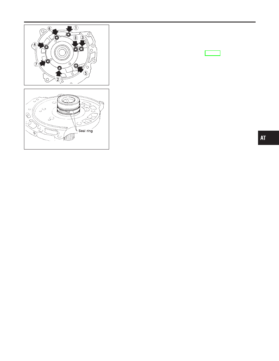
4.
Install oil pump cover on oil pump housing.
a.
Wrap masking tape around splines of oil pump cover assem-
bly to protect seal. Position oil pump cover assembly on oil
pump housing assembly, then remove masking tape.
b.
Tighten bolts in a crisscross pattern. Tighten oil pump cover
bolts to the specified torque. Refer to AT-310.
SAT699H
5.
Install new seal rings carefully after packing ring groove with
petroleum jelly.
I
Do not spread gap of seal ring excessively while install-
ing. The ring may be deformed.
GI
MA
EM
LC
EC
FE
AX
SU
BR
ST
RS
BT
HA
SC
EL
IDX
REPAIR FOR COMPONENT PARTS
Oil Pump (Cont’d)
AT-313