Infiniti I35 (A33). Manual - part 51
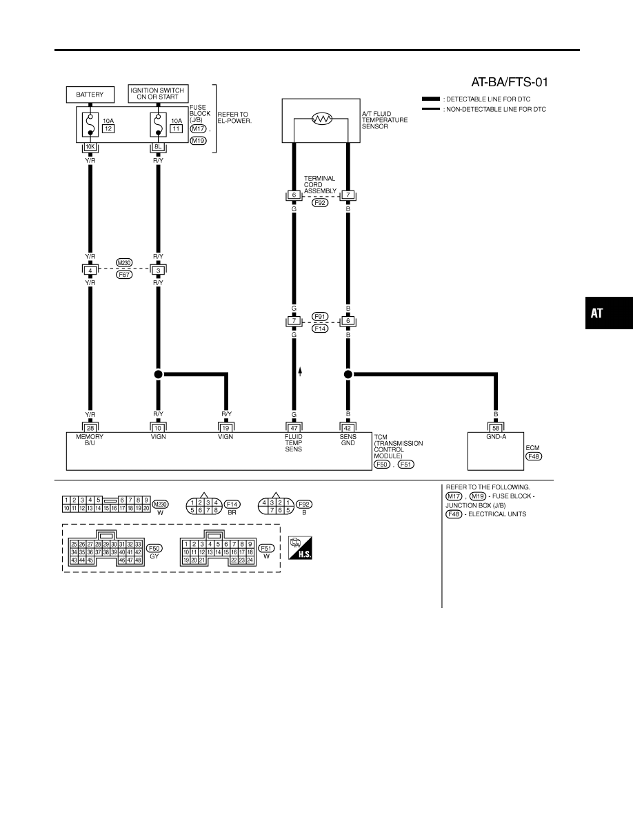
Wiring Diagram — AT — BA/FTS
NHAT0080
MAT487B
GI
MA
EM
LC
EC
FE
AX
SU
BR
ST
RS
BT
HA
SC
EL
IDX
DTC BATT/FLUID TEMP SEN (A/T FLUID TEMP SENSOR CIRCUIT AND TCM
POWER SOURCE)
Wiring Diagram — AT — BA/FTS
AT-201
|
|
|
Wiring Diagram — AT — BA/FTS NHAT0080 MAT487B GI MA EM LC EC FE AX SU BR ST RS BT HA SC EL IDX DTC BATT/FLUID TEMP SEN (A/T FLUID TEMP SENSOR CIRCUIT AND TCM POWER SOURCE) Wiring Diagram — AT — BA/FTS AT-201 |