Infiniti I35 (A33). Manual - part 26
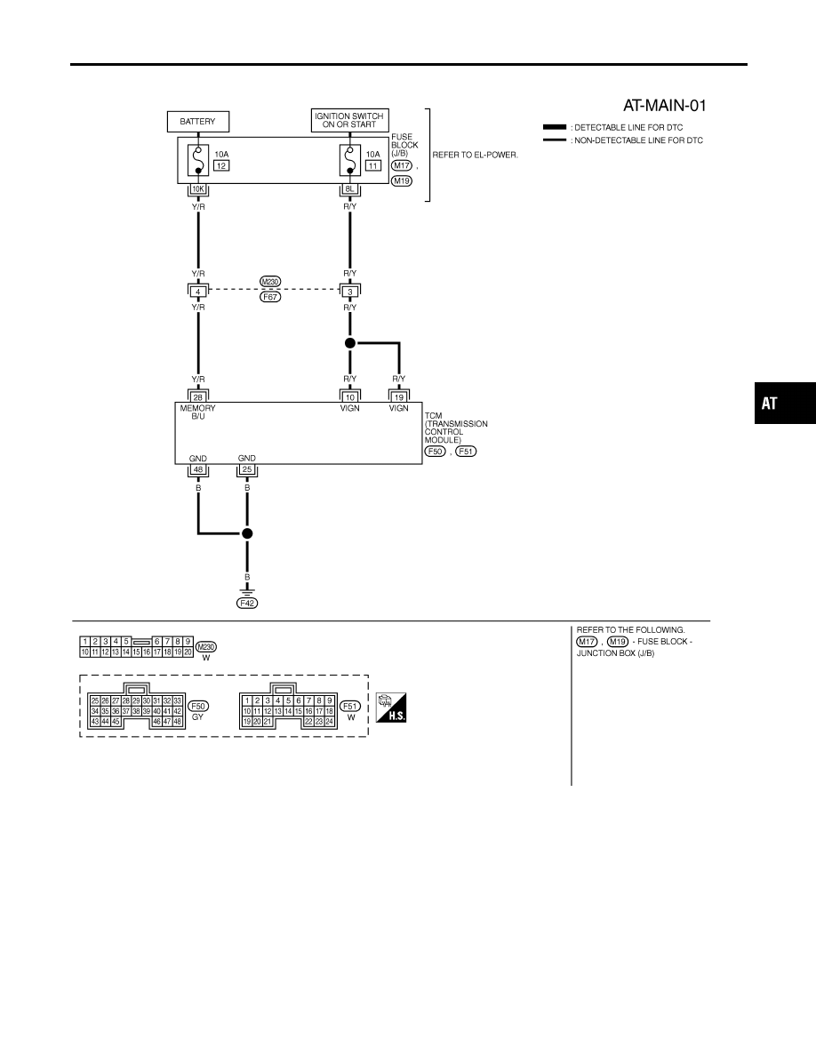
Wiring Diagram — AT — MAIN
NHAT0032
MAT470B
GI
MA
EM
LC
EC
FE
AX
SU
BR
ST
RS
BT
HA
SC
EL
IDX
TROUBLE DIAGNOSIS FOR POWER SUPPLY
Wiring Diagram — AT — MAIN
AT-101
|
|
|
Wiring Diagram — AT — MAIN NHAT0032 MAT470B GI MA EM LC EC FE AX SU BR ST RS BT HA SC EL IDX TROUBLE DIAGNOSIS FOR POWER SUPPLY Wiring Diagram — AT — MAIN AT-101 |