Infiniti I35 (A33). Manual - part 2


  Index      Infiniti     Infiniti I35 (A33) - service repair manual 2004 year


Search            


Content   ..  1  2  3   ..


Infiniti I35 (A33). Manual - part 2


Alphabetical & P No. Index for DTC

NHAT0001

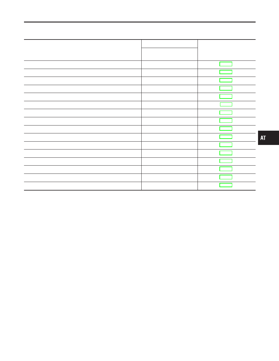
ALPHABETICAL INDEX FOR DTC

NHAT0001S01

Items

(CONSULT-II screen terms)

DTC

Reference page

CONSULT-II

GST*1

A/T 1ST GR FNCTN

P0731

AT-130

A/T 2ND GR FNCTN

P0732

AT-136

A/T 3RD GR FNCTN

P0733

AT-142

A/T 4TH GR FNCTN

P0734

AT-148

A/T TCC S/V FNCTN

P0744

AT-162

ATF TEMP SEN/CIRC

P0710

AT-114

CAN COMM CIRCUIT

U1000

AT-104

ENGINE SPEED SIG

P0725

AT-125

L/PRESS SOL/CIRC

P0745

AT-172

O/R CLTCH SOL/CIRC

P1760

AT-194

PNP SW/CIRC

P0705

AT-108

SFT SOL A/CIRC*2

P0750

AT-178

SFT SOL B/CIRC*2

P0755

AT-183

TCC SOLENOID/CIRC

P0740

AT-157

TP SEN/CIRC A/T*2

P1705

AT-188

VEH SPD SEN/CIR AT*3

P0720

AT-120

*1: These numbers are prescribed by SAE J2012.
*2: When the fail-safe operation occurs, the MIL illuminates.
*3: The MIL illuminates when both the “Revolution sensor signal” and the “Vehicle speed sensor signal” meet the fail-safe condition at
the same time.

GI

MA

EM

LC

EC

FE

AX

SU

BR

ST

RS

BT

HA

SC

EL

IDX

TROUBLE DIAGNOSIS — INDEX

Alphabetical & P No. Index for DTC

AT-5

P NO. INDEX FOR DTC

=NHAT0001S02

DTC

Items

(CONSULT-II screen terms)

Reference page

CONSULT-II

GST*1

P0705

PNP SW/CIRC

AT-108

P0710

ATF TEMP SEN/CIRC

AT-114

P0720

VEH SPD SEN/CIR AT*3

AT-120

P0725

ENGINE SPEED SIG

AT-125

P0731

A/T 1ST GR FNCTN

AT-130

P0732

A/T 2ND GR FNCTN

AT-136

P0733

A/T 3RD GR FNCTN

AT-142

P0734

A/T 4TH GR FNCTN

AT-148

P0740

TCC SOLENOID/CIRC

AT-157

P0744

A/T TCC S/V FNCTN

AT-162

P0745

L/PRESS SOL/CIRC

AT-172

P0750

SFT SOL A/CIRC*2

AT-178

P0755

SFT SOL B/CIRC*2

AT-183

P1705

TP SEN/CIRC A/T*2

AT-188

P1760

O/R CLTCH SOL/CIRC

AT-194

U1000

CAN COMM CIRCUIT

AT-104

*1: These numbers are prescribed by SAE J2012.
*2: When the fail-safe operation occurs, the MIL illuminates.
*3: The MIL illuminates when both the “Revolution sensor signal” and the “Vehicle speed sensor signal” meet the fail-safe condition at
the same time.

TROUBLE DIAGNOSIS — INDEX

Alphabetical & P No. Index for DTC (Cont’d)

AT-6

Precautions for Supplemental Restraint System
(SRS) “AIR BAG” and “SEAT BELT
PRE-TENSIONER”

NHAT0002

The Supplemental Restraint System such as “AIR BAG” and “SEAT BELT PRE-TENSIONER”, used along with
a front seat belt, helps to reduce the risk or severity of injury to the driver and front passenger for certain types
of collision. This system includes seat belt switch inputs and dual stage front air bag modules. The SRS sys-
tem uses the seat belt switches to determine the front air bag deployment, and may only deploy one front air
bag, depending on the severity of a collision and whether the front occupants are belted or unbelted.
Information that is necessary to service the system safely is included in the RS section of this Service Manual.

WARNING:

I

To avoid rendering the SRS inoperative, which could increase the risk of personal injury or death
in the event of a collision which would result in air bag inflation, all maintenance must be performed
by an authorized NISSAN/INFINITI dealer.

I

Improper maintenance, including incorrect removal and installation of the SRS, can lead to per-
sonal injury caused by unintentional activation of the system. For removal of Spiral Cable and Air
Bag Module, see the RS section.

I

Do not use electrical test equipment on any circuit related to the SRS unless instructed to in this
Service Manual. SRS wiring harnesses can be identified by yellow and/or orange harnesses or
harness connectors.

Precautions for On Board Diagnostic (OBD)
System of A/T and Engine

NHAT0003

The ECM has an on board diagnostic system. It will light up the malfunction indicator lamp (MIL) to warn the
driver of a malfunction causing emission deterioration.

CAUTION:

I

Be sure to turn the ignition switch OFF and disconnect the negative battery terminal before any
repair or inspection work. The open/short circuit of related switches, sensors, solenoid valves, etc.
will cause the MIL to light up.

I

Be sure to connect and lock the connectors securely after work. A loose (unlocked) connector will
cause the MIL to light up due to an open circuit. (Be sure the connector is free from water, grease,
dirt, bent terminals, etc.)

I

Be sure to route and secure the harnesses properly after work. Interference of the harness with a
bracket, etc. may cause the MIL to light up due to a short circuit.

I

Be sure to connect rubber tubes properly after work. A misconnected or disconnected rubber tube
may cause the MIL to light up due to a malfunction of the EGR system or fuel injection system,
etc.

I

Be sure to erase the unnecessary malfunction information (repairs completed) from the TCM or
ECM before returning the vehicle to the customer.

SEF289H

Precautions

NHAT0004

I

Before connecting or disconnecting the TCM harness
connector, turn ignition switch OFF and disconnect nega-
tive battery terminal. Failure to do so may damage the
TCM. Because battery voltage is applied to TCM even if
ignition switch is turned off.

GI

MA

EM

LC

EC

FE

AX

SU

BR

ST

RS

BT

HA

SC

EL

IDX

PRECAUTIONS

Precautions for Supplemental Restraint System (SRS) “AIR BAG” and “SEAT BELT PRE-TENSIONER”

AT-7

AAT470A

I

When connecting or disconnecting pin connectors into or
from TCM, take care not to damage pin terminals (bend or
break).
Make sure that there are not any bends or breaks on TCM
pin terminal, when connecting pin connectors.

MEF040DA

I

Before replacing TCM, perform TCM input/output signal
inspection and make sure whether TCM functions prop-
erly or not. (See page AT-98.)

SAT964I

I

After performing each TROUBLE DIAGNOSIS, perform
“DTC (Diagnostic Trouble Code) CONFIRMATION PROCE-
DURE”.
The DTC should not be displayed in the “DTC CONFIRMA-
TION PROCEDURE” if the repair is completed.

I

Before proceeding with disassembly, thoroughly clean the out-
side of the transaxle. It is important to prevent the internal parts
from becoming contaminated by dirt or other foreign matter.

I

Disassembly should be done in a clean work area.

I

Use lint-free cloth or towels for wiping parts clean. Common
shop rags can leave fibers that could interfere with the opera-
tion of the transaxle.

I

Place disassembled parts in order for easier and proper
assembly.

I

All parts should be carefully cleaned with a general purpose,
non-flammable solvent before inspection or reassembly.

I

Gaskets, seals and O-rings should be replaced any time the
transaxle is disassembled.

I

It is very important to perform functional tests whenever they
are indicated.

I

The valve body contains precision parts and requires extreme
care when parts are removed and serviced. Place disas-
sembled valve body parts in order for easier and proper
assembly. Care will also prevent springs and small parts from
becoming scattered or lost.

I

Properly installed valves, sleeves, plugs, etc. will slide along
bores in valve body under their own weight.

I

Before assembly, apply a coat of recommended ATF to all

PRECAUTIONS

Precautions (Cont’d)

AT-8


Content   ..  1  2  3   ..