Infiniti G37 Coupe. Manual - part 968


  Index      Infiniti     Infiniti G37 Coupe - service repair manual 2008 year


Search            


Content   ..  966  967  968  969   ..


Infiniti G37 Coupe. Manual - part 968


PCS

POWER DISTRIBUTION SYSTEM

PCS-41

< FUNCTION DIAGNOSIS >

[POWER DISTRIBUTION SYSTEM]

C

D

E

F

G

H

I

J

K

L

B

A

O

P

N

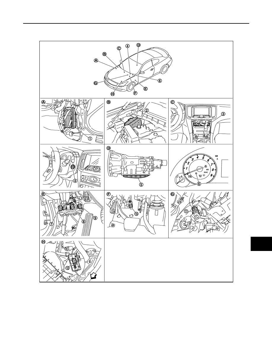
Component Parts Location

INFOID:0000000001675257

JMMIA0004ZZ

1.

BCM M118, M119, M121, M122, M123 2.

IPDM E/R E5, E6, E7

3.

Unified meter and A/C AMP. M66, M67

4.

Push button ignition switch M50

5.

TCM F151

6.

Combination meter (Key warning 
lamp) M53

7.

Ignition relay

8.

Accessory relay

9.

Blower relay

10.

Clutch interlock switch E111

11.

Stop lamp switch E110

12.

ICC brake hold relay

A.

Dash side lower (Passenger side).

B.

Engine room dash panel (RH).

C.

Behind cluster lid C.

PCS-42

< FUNCTION DIAGNOSIS >

[POWER DISTRIBUTION SYSTEM]

POWER DISTRIBUTION SYSTEM

Component Description

INFOID:0000000001675258

D.

Inside of A/T (built into A/T).

E.

View with dash side LH removed.

F

View with instrument driver lower cov-
er removed.

G.

View with instrument driver lower cov-
er removed.

H.

Left view of engine room

BCM

Reference

IPDM E/R

PCS-4

Ignition relay (Built-in IPDM E/R)

PCS-18

Ignition relay (Built-in fuse block)

PCS-50

Accessory relay

PCS-54

Blower relay

PCS-60

Stop lamp switch

SEC-58

Park/neutral position switch (A/T models)

SEC-72

Clutch inter lock switch (M/T models)

SEC-112

Push-button ignition switch

SEC-60

PCS

DIAGNOSIS SYSTEM (BCM)

PCS-43

< FUNCTION DIAGNOSIS >

[POWER DISTRIBUTION SYSTEM]

C

D

E

F

G

H

I

J

K

L

B

A

O

P

N

DIAGNOSIS SYSTEM (BCM)

COMMON ITEM

COMMON ITEM : CONSULT-III Function (BCM - COMMON ITEM)

INFOID:0000000001675259

APPLICATION ITEM

CONSULT-III performs the following functions via CAN communication with BCM.

SYSTEM APPLICATION

BCM can perform the following functions for each system.
NOTE:
It can perform the diagnosis modes except the following for all sub system selection items.

*: This item is displayed, but is not used. 

FREEZE FRAME DATA (FFD) AND IGN COUNTER

Freeze Frame Data

The BCM records the following condition at the moment a particular DTC is detected.
• Vehicle Speed
• Odd Trip Meter

Diagnosis mode

Function Description

Work Support

Changes the setting for each system function.

Self Diagnostic Result

Displays the diagnosis results judged by BCM.

CAN DIAG SUPPORT MNTR

Monitors the reception status of CAN communication viewed from BCM. Refer to CONSULT-III opera-
tion manual.

Data Monitor

The BCM input/output signals are displayed.

Active Test

The signals used to activate each device are forcibly supplied from BCM.

Ecu Identification

The BCM part number is displayed.

Configuration

This function is not used even though it is displayed.

System

Sub system selection item

Diagnosis mode

Work Support

Data Monitor

Active Test

Door lock

DOOR LOCK

×

×

×

Rear window defogger

REAR DEFOGGER

×

×

Warning chime

BUZZER

×

×

Interior room lamp timer

INT LAMP

×

×

×

Exterior lamp

HEAD LAMP

×

×

×

Wiper and washer

WIPER

×

×

×

Turn signal and hazard warning lamps

FLASHER

×

×

×

Air conditioner*

AIR CONDITONER

×

Intelligent Key system

INTELLIGENT KEY

×

×

×

Combination switch

COMB SW

×

BCM

BCM

×

IVIS - NATS

IMMU

×

×

Interior room lamp battery saver

BATTERY SAVER

×

×

×

Trunk open

TRUNK

×

Vehicle security system

THEFT ALM

×

×

×

RAP system

RETAINED PWR

×

Signal buffer system

SIGNAL BUFFER

×

×

TPMS

TPMS (AIR PRESSURE MONITOR)

×

×

×

PCS-44

< FUNCTION DIAGNOSIS >

[POWER DISTRIBUTION SYSTEM]

DIAGNOSIS SYSTEM (BCM)

• Vehicle Condition (BCM detected condition)

IGN Counter

IGN counter indicates the number of times that ignition switch is turned ON after DTC is detected.
• The number is 0 when a malfunction is detected now.
• The number increases like 1 

 2 

 3...38 

 39 after returning to the normal condition whenever ignition

switch OFF 

 ON.

• The number is fixed to 39 until the self-diagnosis results are erased if it is over 39.

INTELLIGENT KEY

INTELLIGENT KEY : CONSULT-III Function (BCM - INTELLIGENT KEY)

INFOID:0000000001675260

BCM CONSULT-III FUNCTION

CONSULT-III performs the following functions via CAN communication with BCM.

WORK SUPPORT

CONSULT screen terms

Description

SLEEP>LOCK

While turning BCM status from low power consumption mode to normal mode (Power supply 
position is “LOCK”)

SLEEP>OFF

While turning BCM status from low power consumption mode to normal mode (Power supply 
position is “OFF”.)

LOCK>ACC

While turning power supply position from “LOCK” to “ACC”

ACC>ON

While turning power supply position from “ACC” to “IGN”

RUN>ACC

While turning power supply position from “RUN” to “ACC” (Vehicle is stopping and selector 
lever is except P position.)

CRANK>RUN

While turning power supply position from “CRANKING” to “RUN” (From cranking up the en-
gine to run it)

RUN>URGENT

While turning power supply position from “RUN“ to “ACC” (Emergency stop operation)

ACC>OFF

While turning power supply position from “ACC” to “OFF”

OFF>LOCK

While turning power supply position from “OFF” to “LOCK”

OFF>ACC

While turning power supply position from “OFF” to “ACC”

ON>CRANK

While turning power supply position from “IGN” to “CRANKING”

OFF>SLEEP

While turning BCM status from normal mode (Power supply position is “OFF”.) to low power 
consumption mode

LOCK>SLEEP

While turning BCM status from normal mode (Power supply position is “LOCK”.) to low pow-
er consumption mode

LOCK

Power supply position is “LOCK” (Ignition switch OFF with steering is locked.)

OFF

Power supply position is “OFF” (Ignition switch OFF with steering is unlocked.)

ACC

Power supply position is “ACC” (Ignition switch ACC)

ON

Power supply position is “IGN” (Ignition switch ON with engine stopped)

ENGINE RUN

Power supply position is “RUN” (Ignition switch ON with engine running)

CRANKING

Power supply position is “CRANKING” (At engine cranking)

Diagnosis mode

Function Description

WORK SUPPORT

Changes the setting for each system function.

SELF-DIAG RESULTS

Displays the diagnosis results judged by BCM.

DATA MONITOR

The BCM input/output signals are displayed.

ACTIVE TEST

The signals used to activate each device are forcibly supplied from BCM.


Content   ..  966  967  968  969   ..